
Device for pneumatically driving two free flexible mechanical arms and method for controlling device

A flexible mechanical arm and pneumatic drive technology, applied in the field of flexible robots, can solve problems affecting the normal operation of the mechanical arm, low rigidity of the flexible mechanical arm, low-frequency large-scale vibration, etc., and achieve the effect of simple structure, high control precision and fast work

Inactive Publication Date: 2012-01-04
SOUTH CHINA UNIV OF TECH
View PDF5 Cites 40 Cited by
  • Summary
  • Abstract
  • Description
  • Claims
  • Application Information

AI Technical Summary

Problems solved by technology

Compared with the commonly used rigid manipulator, the flexible manipulator has the advantages of light weight, large load, dexterity, low energy consumption, and high efficiency. During the process, it is easy to generate long-term continuous low-frequency and large-value vibration, which seriously affects the normal operation of the robotic arm.

Method used


Image

  • Device for pneumatically driving two free flexible mechanical arms and method for controlling device
  • Device for pneumatically driving two free flexible mechanical arms and method for controlling device

Examples


Embodiment

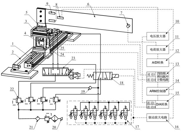
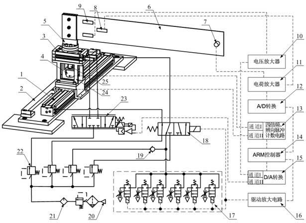
[0042] Such as figure 1As shown, one end of the flexible mechanical arm 6 is connected to the swing flange of the swing cylinder 3 through the swing flange mechanical connection device 5 . The swing flange of the swing cylinder 3 is connected with the rotating shaft of the photoelectric encoder 4 through a shaft coupling 25, and the photoelectric encoder 4 is fixedly connected with the base of the swing cylinder 3, so that the rotation angle of the swing cylinder 3 rotating flange can be detected. A plurality of piezoelectric ceramic sheets are pasted near the mechanical connection device 5 of the flexible mechanical arm 6 and the swing cylinder to rotate the swing flange, respectively as the piezoelectric sheet sensor 8 and the piezoelectric driver 9, and the piezoelectric driver 9 is located on the flexible The upper and lower sides of the transverse midline near the fixed end of the mechanical arm 6 are 2.5 cm away from the fixed end in the length direction, and 2 cm away f...


PUM


Abstract

The invention discloses a device for pneumatically driving two free flexible mechanical arms and a method for controlling the device. The device comprises a flexible mechanical arm body, a pneumatic driving part and a control part, wherein one end of the flexible mechanical arm body is a free end, and the other end of the flexible mechanical arm body is a fixed end; the fixed end is arranged on an oscillating flange plate of an oscillating cylinder through an oscillating flange plate mechanical connection device; a rotation angle of the oscillating cylinder is detected by a photoelectric coder; the displacement of a rodless movement cylinder is detected by a linear grating ruler; a plurality of piezoelectric ceramic chips are adhered to the fixed end of the flexible mechanical arm body and respectively serve as a piezoelectric sensor and a piezoelectric driver; an acceleration sensor is arranged at the free end; the piezoelectric sensor or the acceleration sensor can detect the vibration of the flexible mechanical arms; the pneumatic driving part consists of two pneumatic channels which are respectively used for driving the movement of the rodless movement cylinder and the oscillation of the oscillating cylinder; and the control part is used for processing the detected movement, rotation and vibration signals of the flexible mechanical arms and performing corresponding processing.

Description

technical field [0001] The invention relates to the field of flexible robots, in particular to a pneumatically driven two-degree-of-freedom flexible mechanical arm device and a control method. Background technique [0002] As an important tool in the modern automation industry, the robotic arm has been widely used in aerospace, high-precision machining and measurement, medical equipment and other fields due to its large working space, good flexibility, and the ability to work in environments that humans cannot reach. Wide range of applications. Compared with the commonly used rigid manipulators, flexible manipulators have the advantages of light weight, large load, dexterity, low energy consumption, and high efficiency. During the process, it is easy to generate long-term continuous low-frequency and large-value vibration, which seriously affects the normal operation of the robotic arm. In recent years, the research on the active vibration control of flexible manipulators ...

Claims


Application Information

Patent Timeline
Patent Type & Authority Applications(China)
IPC IPC(8): B25J9/16B25J19/00
Inventor 邱志成王斌
Owner SOUTH CHINA UNIV OF TECH
Learn More