Double-layer rail three-dimensional rapid transit system

A transportation system, double-deck technology, applied in sustainable transportation, combined railway system, track, etc., can solve the problem of slow speed of ordinary public transport and unsuitable for fast-paced urban life, viaduct piers occupying pavement space, operating speed and efficiency limitations, etc. problems, to achieve the effect of small floor space, convenience for passengers, and safety

Inactive Publication Date: 2012-01-04
张佳伟
View PDF0 Cites 2 Cited by
  • Summary
  • Abstract
  • Description
  • Claims
  • Application Information

AI Technical Summary

Problems solved by technology

[0002] At present, the urban land resources are limited, the space is small and crowded, and the traffic congestion is very serious. Due to the limitation of road resources and the influence of traffic lights, the speed and efficiency of existing vehicles are also limited. Vehicles are miserable. To cope with the increasing passenger flow, a viaduct design is adopted, but the viaduct piers occupy the road space. Many cities build new subways and light rails, but the cost of subways and light rails is high, the operating efficiency of taxis is low, and BRT occupies road resources. Ordinary buses The slow speed does not adapt to the fast-paced life of the city. These means of transportation and facilities cannot effectively solve the congestion, and many cities are facing or will soon face the worldwide problem of traffic congestion. The current solutions to traffic congestion, such as: traffic restrictions, Charges and so on can only play a role in mitigating. The real fundamental solution requires a convenient and practical means of transportation. It needs to have the advantages of high efficiency and fast speed, can quickly evacuate a large number of passenger flows, and can save money in terms of safety costs and other aspects. To be excellent, this ideal means of transportation will gradually become the first choice for people to travel

Method used


Image

  • Double-layer rail three-dimensional rapid transit system
  • Double-layer rail three-dimensional rapid transit system
  • Double-layer rail three-dimensional rapid transit system

Examples


Embodiment Construction

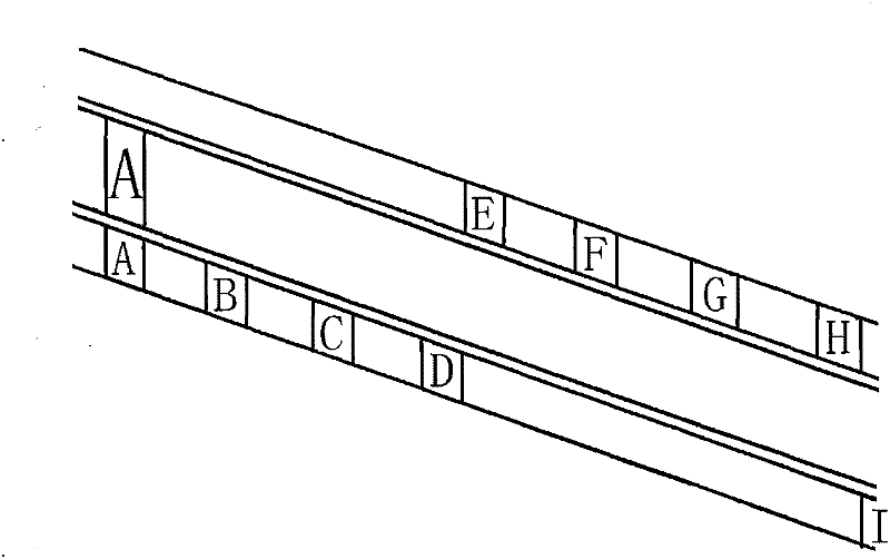
[0025] figure 1 It is the operation principle diagram of the upper system. In the figure, two parallel lines indicate the main car and the sub-car track. The main car track width is the main car width, and the sub-car track width is the sub-car width. There is a sub-vehicle marked with ABCD in 100 meters. Now suppose the main car is at position A, and the sub-vehicle at B receives the wireless signal sent by the main car. The sub-vehicle at B starts to run. When it reaches point C, the speed of the two vehicles reaches the same speed, and then: Open the door at the same time, exchange passengers, close the door at the same time, separate the car and decelerate and finally stop at the D position, while the main car continues to run at the same speed.

[0026] All sub-cars operate in this way, for example: C-discipline car passes through D to exchange passengers and finally stops at a certain position in front of D, such as E, and so on. After the main car passes through, all su...


PUM


Abstract

The invention relates to a rail traffic tool capable of effectively solving the problem of urban traffic jam, in particular to a double-layer running rail system. A suspension train runs on the lower layer and shares a rail with a main vehicle of the upper layer; a set of system is arranged on the upper layer and consists of the main vehicle and a branched vehicle, the main vehicle continuously runs on a main vehicle rail, the branched vehicle can stop at any position of a branched vehicle rail, and two rails are close to each other; in operation, before the main vehicle arrives, passengers enters the branched vehicle, and the branched vehicle is started; when the speeds of the two vehicles are the same, the doors of the two vehicles are opened at the same time, the passengers are exchanged, the branched vehicle is separated, slows down and finally stops, and the passengers get off the vehicle. A light rail to be erected passes overhead a six-layer cell, pedestrian paths on the upper and lower layers are used for waiting the vehicle, and a lift is arranged at every one hundred meter along the line; and after the passengers are delivered to the height of two-layer pedestrian paths, the system is uniformly controlled and runs regularly and stably.

Description

(1) Technical field [0001] The invention is suitable for solving the problem of traffic congestion in the city, and is a particularly prominent means of transportation in terms of speed and efficiency. (2) Background technology [0002] At present, the urban land resources are limited, the space is small and crowded, and the traffic congestion is very serious. Due to the limitation of road resources and the influence of traffic lights, the speed and efficiency of existing vehicles are also limited. Vehicles are miserable. To cope with the increasing passenger flow, a viaduct design is adopted, but the viaduct piers occupy the road space. Many cities build new subways and light rails, but the cost of subways and light rails is high, the operating efficiency of taxis is low, and BRT occupies road resources. Ordinary buses The slow speed does not adapt to the fast-paced life of the city. These means of transportation and facilities cannot effectively solve the congestion, and m...

Claims


Application Information

Patent Timeline
Patent Type & Authority Applications(China)
IPC IPC(8): B61B15/00B61B1/00E01C1/04
CPCY02T30/40Y02T30/00
Inventor 张佳伟
Owner 张佳伟
Why Eureka
Try Eureka