Re-combustion injector of combustor of re-combustion supercritical pressure gas-liquid phase fuel generator

A technology of fuel generators and injectors, which is applied in the direction of burners, production fluids, wellbore/well components, etc., and can solve the design concept of simultaneous combustion of gas-liquid two-phase fuels and the inability to satisfy two-phase fluid injection at the same time Characteristic requirements, the inability to change the combustion mode of the generator, etc., to achieve the effect of avoiding burning and damage, flexible cooling mode and high reliability

Active Publication Date: 2012-01-04
关兵 +2
View PDF6 Cites 6 Cited by
  • Summary
  • Abstract
  • Description
  • Claims
  • Application Information

AI Technical Summary

Problems solved by technology

However, according to the field test, although the above scheme solved the burning or damage problem of the top of the combustion chamber in the original design working condition, when the injection pressure of the generator increased, the flow increased and the long-term continuous operation, the cyclone, the top of the combustion chamber and the inner The lining and other components still suffered from severe burning, which caused consequences such as burning eccentricity and lining damage, which affected the normal operation of the equipment
In addition, in the disclosed invention designs, single-phase nozzles are usually used, but due to the different flow characteristics of gas-liquid two-phase fluids, the nozzle design requirements are quite different. Therefore, the previous single-phase nozzles often cannot meet the requirements of two-phase fluids The injection characteristics requirements, that is, the design concept of simultaneous combustion of gas-liquid two-phase fuel cannot be met, especially the original combustion method that the generator is concentrated on the top of the combustion chamber cannot be changed

Method used


Image

  • Re-combustion injector of combustor of re-combustion supercritical pressure gas-liquid phase fuel generator
  • Re-combustion injector of combustor of re-combustion supercritical pressure gas-liquid phase fuel generator
  • Re-combustion injector of combustor of re-combustion supercritical pressure gas-liquid phase fuel generator

Examples


Embodiment 1

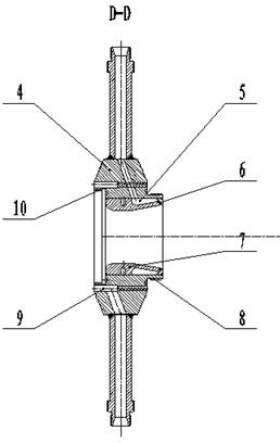
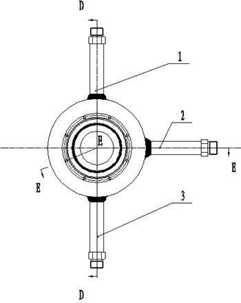
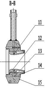
[0038] like figure 1 , figure 2 , image 3 As shown, the components in the figure are: gas phase nozzle 1, liquid phase nozzle 2, water nozzle 3, afterburning injector housing 4, and throat liner 7.

[0039] Wherein, a gas phase cavity 5 and a gas phase nozzle 6 are provided in the internal channel of the gas phase connector 1, a fuel nozzle 11 is provided in the internal channel of the liquid phase connector 2, and a liquid collecting chamber 9 and a liquid collecting chamber 9 are provided in the internal channel of the water connector 3. The water hole 13; the two end faces of the afterburner injector housing 4 are spherical end faces 15, and its front end has an internal connecting thread 10 and a corresponding sealing groove for connecting the air and water combination redundant cooling jacket assembly of the pre-combustion chamber 12. Its rear end has an external connection thread 8 and a sealing groove 14 for connecting the water cooling jacket of the supplementary c...

Embodiment 2

[0043] like Figure 4 , Figure 5 or Image 6 , Figure 7 As shown, the components in the figure are: gas phase nozzle 1 or liquid phase nozzle 2, water nozzle 3, afterburning injector housing 4, throat liner 7.

[0044] Among them, the afterburning injector shell 4 is provided with a water connection nozzle 3, a gas phase connection nozzle 1 or a liquid phase connection nozzle 2, and a gas phase chamber 5 and a gas phase nozzle 6 or a liquid phase connection nozzle are provided in the internal passage of the gas phase connection nozzle 1. A fuel nozzle 11 is provided in the inner passage of the nozzle 2, and a liquid collection chamber 9 and a water passage hole 13 are provided in the inner passage of the water joint nozzle 3; the two end faces of the afterburning injector housing 4 are spherical end faces 15, and Its front end has an internal connecting thread 10 and a corresponding sealing groove 12 for connecting the air and water combined redundant cooling jacket assem...

Embodiment 3

[0048] like Figure 8 , Figure 9 or Figure 10 , Figure 11 As shown, the components in the figure are: gas phase nozzle 1 or liquid phase nozzle 2, afterburning injector housing 4, throat liner 7.

[0049] Among them, the afterburning injector housing 4 is provided with a gas-phase nozzle 1 or a liquid-phase nozzle 2, and the internal passage of the gas-phase nozzle 1 is provided with a gas-phase chamber 5 and a gas-phase nozzle 6, and the internal passage of the liquid-phase nozzle 2 A fuel nozzle 11 is provided in the middle, and a liquid collecting chamber 9 and a water hole 13 are provided on the supplementary combustion injector housing 4; the two end surfaces of the supplementary combustion injector housing 4 are spherical end surfaces 15, and its front end has The internal connection thread 10 and the corresponding sealing groove 12 connected to the air and water combination redundant cooling jacket assembly of the pre-combustion chamber have an external connection...


PUM


Abstract

The invention discloses a re-combustion injector of a combustor of a re-combustion supercritical pressure gas-liquid phase fuel generator and relates to oil extraction equipment in the oilfield. A gas-phase cavity (5) and a gas-phase nozzle (6) are arranged in an internal channel of a gas-phase joint (1); a fuel nozzle (11) is arranged in an internal channel of a liquid-phase joint (2); a liquid-collecting cavity (9) and a drain hole (13) are arranged in an internal channel of a water joint (3); two end surfaces of a re-combustion injector shell (4) are spherical end surfaces (15); the gas-phase joint (1), the liquid-phase joint (2) and the water joint (3) are connected with the re-combustion injector shell (4); a throat insert (7) is also connected with the re-combustion injector shell (4); and the re-combustion injector shell (4) is clamped and fixed between a pre-combustion chamber shell and a re-combustion chamber shell. The invention has the advantages of changing the combustion mode of the traditional steam injection generator, dividing a disposable combustion mode integrated on the top of the combustion chamber into a mode with a pre-combustion part and a re-combustion partthrough a re-combustion type combustion method and realizing the combustion of two phases of fuels at the same time.

Description

technical field [0001] The invention relates to oil production equipment in oil fields, in particular to a supplementary combustion injector device for the combustion chamber of a supplementary combustion type supercritical pressure gas-liquid two-phase fuel steam injection generator (also known as a composite heat carrier generator). Background technique [0002] Since the advent of steam injection generator for more than ten years, multi-well pilot tests have been carried out in shallow oil reservoirs and high-permeability medium-deep oil reservoirs in several major oilfields in China, such as Daqing, Shengli, Liaohe, and Xinjiang. The test results show that the oil-increasing mechanism of the equipment is feasible and can be organically combined with a number of existing oil-recovery processes, and certain oil-increasing effects have been achieved. However, with the deepening of reservoir development, several composite heat carrier generators disclosed in my country have ...

Claims


Application Information

Patent Timeline
Patent Type & Authority Applications(China)
IPC IPC(8): F23D17/00E21B43/24
Inventor 关兵刘殿玺
Owner 关兵
Why Eureka
Try Eureka