Distillate yield improving vacuum distillation method and device

A distillation method and a technology for a vacuum distillation column, which are applied in the field of vacuum distillation methods and devices, can solve problems such as the limited function of a flash column, and achieve the effects of being conducive to capacity expansion, reducing pipe diameter, and high extraction rate.

Active Publication Date: 2012-01-11
CHINA PETROLEUM & CHEM CORP +1
View PDF7 Cites 12 Cited by
  • Summary
  • Abstract
  • Description
  • Claims
  • Application Information

AI Technical Summary

Problems solved by technology

However, when the bottom oil of the atmospheric tower enters the flash tower, since the temperature of the bottom oil of the atmospheric tower is relatively low, and the vacuum degree of the flash tower in front of the furnace is relatively low, the effect of flash vaporization of the flash tower is limited, and the flash The gas phase at the top of the steamer enters the vacuum tower, which is equivalent to segmental feeding of the vacuum tower after flash evaporation, without fundamentally changing the fractionation effect of the vacuum tower

Method used


Image

  • Distillate yield improving vacuum distillation method and device
  • Distillate yield improving vacuum distillation method and device

Examples


Embodiment 1

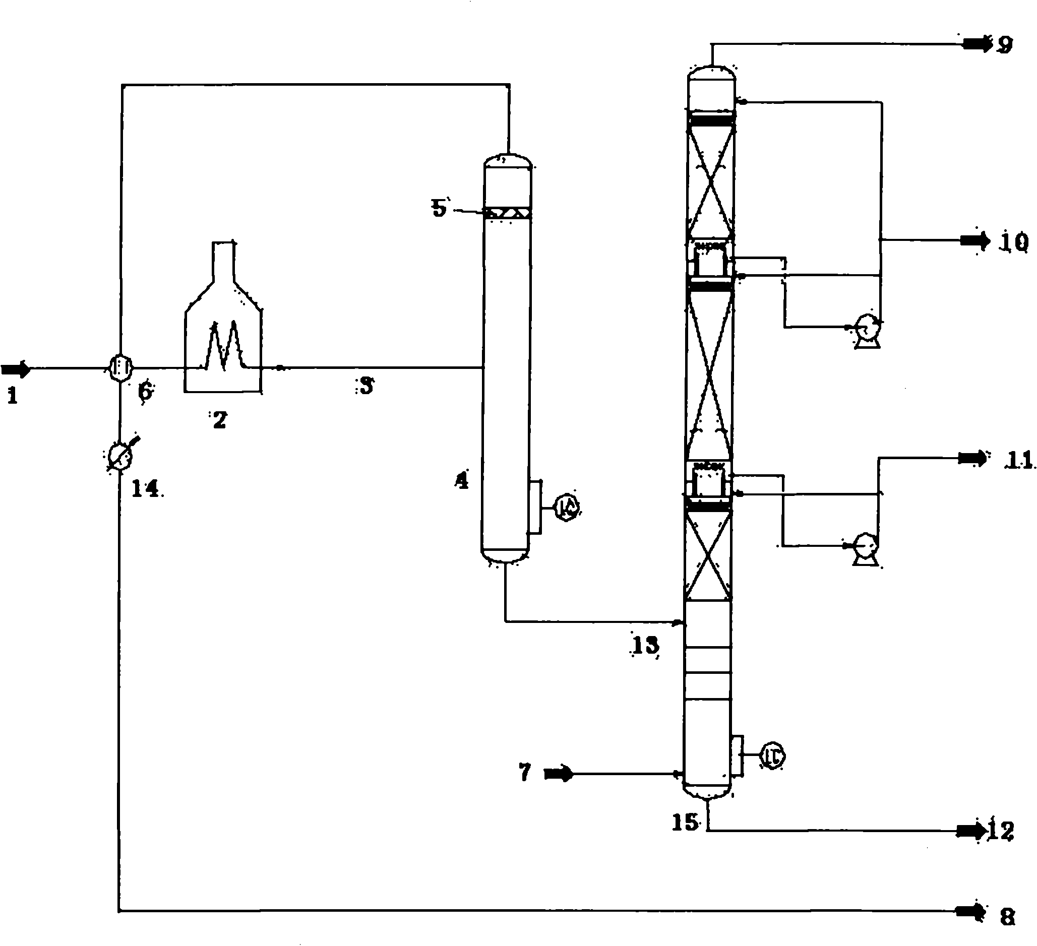
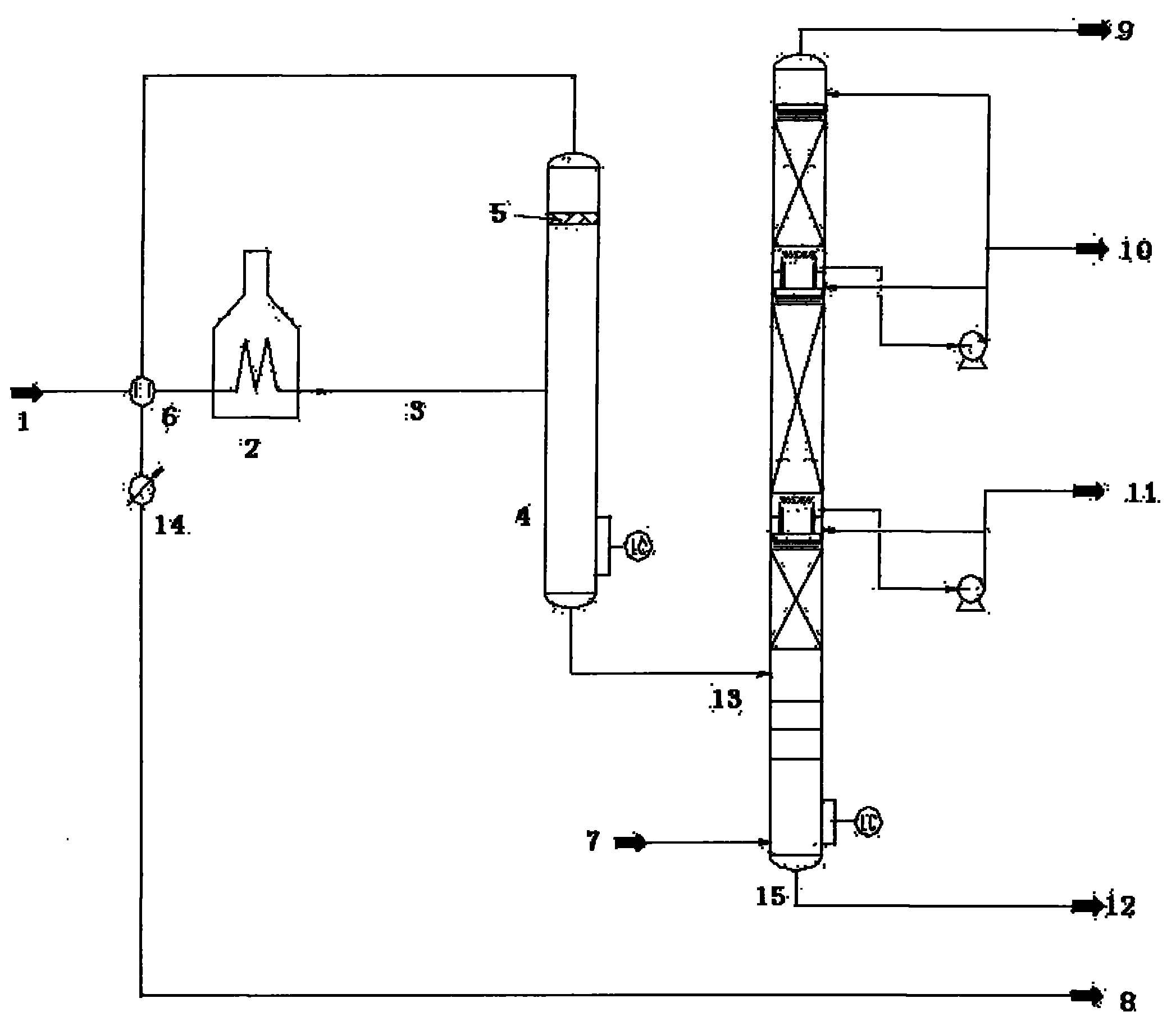
[0030] The method of the present invention is used in the design of a new crude oil atmospheric and vacuum device, and the process flow of the decompression part and the accompanying figure 1 Same as shown.

[0031] The processing capacity of the decompression device is 1.2 million tons per year, and the decompression process includes a decompression furnace, a flash tank, and a decompression tower. The decompression tower is a structured packing tower, which adopts wet process operation. The steam blowing volume at the bottom of the tower is 1% of the tower feed, the operating pressure at the top of the tower is 1.315kPa, and the pressure drop of the whole tower is 600Pa~750Pa.

[0032] The constant bottom oil 1 is fed into the vacuum distillation device at 150 tons / hour, heated to 390°C-400°C by the vacuum furnace 2, and then enters the vacuum flash tank 4 through the vacuum transfer line 3. The flash tank is directly connected with the vacuum tower, and the pressure of the...

Embodiment 2

[0038] The method of the present invention is used for the expansion and transformation of a certain crude oil atmospheric and vacuum device. The normal pressure part is the same as the conventional atmospheric and vacuum device, and the decompression part figure 1 The schematic diagram of the process flow of the vacuum distillation method for improving the extraction rate shown mainly includes a vacuum furnace, a flash tank, and a vacuum tower.

[0039] The decompression tower is a structured packing tower, the operating pressure at the top of the tower is 1.315kPa, and the pressure drop of the whole tower is 600Pa~750Pa.

[0040] The constant bottom oil 1 enters the vacuum distillation device, is heated to 390°C-400°C by the vacuum furnace 2, and then enters the vacuum flash tank 4 from the transition section 3 of the vacuum-to-oil line. The flash tank is directly connected with the vacuum tower, and the pressure of the flash tank is 13kPa. After the adiabatic flash, the fla...


PUM


Abstract

The invention discloses a distillate yield improving vacuum distillation method and device. A flash vaporization vessel is arranged on an oil transfer line between a vacuum furnace and a vacuum distillation tower. Vacuum distillation raw materials enter the oil transfer line and the flash vaporization vessel after being heated by the vacuum furnace. Gas liquid separation is carried out in the flash vaporization vessel: liquid discharged from the bottom of the flash vaporization vessel, namely flash bottom oil, is introduced into the vacuum distillation tower; and gas discharged from the top of the flash vaporization vessel, namely flash top gas, is led out of the device after being condensed into liquid. According to the vacuum distillation method and device with the flash vaporization vessel arranged behind the vacuum furnace, on one hand, the yield of vacuum distillate is increased, on the other hand, a conventional decompression oil transfer line low-speed section is omitted, the operation load of the vacuum tower is reduced, and the diameter of the vacuum tower can be appropriately reduced, so equipment investment is saved, and the operating cost is reduced.

Description

technical field [0001] The invention belongs to the field of petroleum refining, and in particular relates to a vacuum distillation method and device for increasing extraction rate and reducing energy consumption in vacuum distillation of crude oil. technical background [0002] Atmospheric and vacuum distillation process of crude oil in refinery is the first process of petroleum refining. It divides crude oil into components with different distillation ranges by distillation to meet the process requirements of products and downstream devices for raw materials. The level of its light oil yield and the size of energy consumption directly affect the economic benefits of petroleum refining. The conventional atmospheric and vacuum distillation process of crude oil mostly adopts the process of "two furnaces and three towers": the crude oil is pretreated and enters the primary distillation tower (or flash tower), and then is heated in the normal pressure furnace and enters the atm...

Claims


Application Information

Patent Timeline
Patent Type & Authority Applications(China)
IPC IPC(8): C10G53/00C10G7/06
Inventor 张龙王海波齐慧敏刘忠信
Owner CHINA PETROLEUM & CHEM CORP
Why Eureka
Try Eureka