Air supplying device of blast furnace as well as combustion method and oxygen-enriching method of injected coal powder thereof

An air supply device and a blast furnace technology, which are applied in the blast furnace air supply device, blast furnace coal injection technology and blast furnace air supply field, can solve the problems of not becoming a practical technology, limited actual effect, and hindering blast furnace tuyere opening and blocking operation, etc.

Inactive Publication Date: 2012-01-11
张昭贵
View PDF8 Cites 6 Cited by
  • Summary
  • Abstract
  • Description
  • Claims
  • Application Information

AI Technical Summary

Problems solved by technology

Unfortunately, because the cyclone is too short, it is only equivalent to increasing the preheating time of pulverized coal in the direct blowpipe for less than 10ms in advance, so that the practical effect of the invention is limited; and because its position is too far ahead, it hinders The tuyere opening and tuyere blocking operations under the normal production conditions of the blast furnace have not been practically applied in the blast furnace production
Its problem is: the length of the straight blowing pipe is generally about 1.5-2m, and the residence time of pulverized coal in it will exceed the residence time in the tuyere swirl area (generally 50ms), and the excess coefficient of air in the direct blowing pipe is 2-2m. 3 or more, far exceeding the need for complete combustion of pulverized coal
However, in view of the fact that the oxygen-coal gun cannot solve its own service life problem technically, the coal injection technology using the oxygen-coal gun to implement local oxygen enrichment has never become a practical technology that is popularized and widely used in actual production.

Method used


Image

  • Air supplying device of blast furnace as well as combustion method and oxygen-enriching method of injected coal powder thereof
  • Air supplying device of blast furnace as well as combustion method and oxygen-enriching method of injected coal powder thereof
  • Air supplying device of blast furnace as well as combustion method and oxygen-enriching method of injected coal powder thereof

Examples


Embodiment Construction

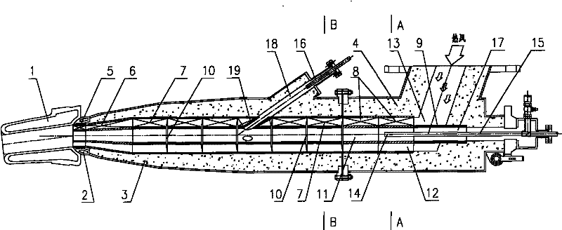
[0047] Such as figure 1 Among them, a blast furnace air supply device is composed of a straight blow pipe 3, an elbow 4 and pipe bricks 5, 6, 7, 8, and 9. The convex spherical end 2 of the straight blow pipe 3 in contact with the tuyere 1 is a water cooling structure. From the peephole channel 17 in the elbow 4 to the entire hot air channel 13 at the outlet of the straight blow pipe 3, use A, B, C, D, E type bricks 5, 6, 7, 8, 9 from the straight blow pipe 3 outlet in turn Start the masonry and build it until the peephole passage 17 of the elbow 4. Except for the E-type brick 9 which is a tube, the A, B, C, and D-type bricks 5, 6, 7, and 8 are all double-layered, and each has an inner tube 21 and an outer tube 22. Each of A, B, C, D type bricks 5, 6, 7, 8 are built according to the method of close contact between the outer tube 22 and the inner tube 21 aligned with each other. The outer wall of their outer tube 22 is in close contact with the inner wall of the hot air duct 13 ...


PUM


Abstract

The invention provides an air supplying device of a blast furnace. Pipeline bricks are wholly or partially installed from a channel opening of a peephole to a whole hot air channel of a belly pipe outlet so that the hot air channel is divided into inner and outer two layers, namely a central channel and an annular channel; and hot air is wholly or partially isolated between the central channel and the annular channel. According to a combustion method of injected coal powder provided by the invention, a spraying gun is inserted to the central channel to carry out coal powder injection; after the injected coal powder is partially combusted or heated in the central channel, the injected coal powder and the hot air coaxially enter into an air opening and the furnace to be completely combusted. According to an oxygen-enriching method provided by the invention, oxygen gas is limited in the central channel to be mixed with less hot air so that a partial oxygen-enriched atmosphere which is good for combusting the coal powder is formed. A secondary coal injection technology which is firstly proposed and reliably realized and is carried out at the outlet of the central channel since the first coal injection patent technology in 1926 is also called as a coaxial coal injection technology.

Description

Technical field [0001] The invention belongs to the technical field of blast furnace ironmaking, and relates to blast furnace coal injection technology and blast furnace air supply technology, in particular to a blast furnace air supply device, and also relates to a blast furnace injection pulverized coal combustion method and a blast furnace injection pulverized coal combustion method and an oxygen enrichment method for blast furnace injection pulverized coal. Background technique [0002] As we all know, the existing method of blast furnace injection of pulverized coal is: on the straight blowing pipe of each tuyere, one or two coal injection guns are inclined at an angle of 10 to 13° with the center line of the straight blowing pipe. Insert the straight blowing pipe, the point where the center line of the coal injection gun and the center line of the straight blowing pipe intersect is located in the tuyere channel, and the gun head extends 100 to 300mm into the tuyere channel a...

Claims


Application Information

Patent Timeline
Patent Type & Authority Applications(China)
IPC IPC(8): C21B7/16F27D3/18
Inventor 张昭贵
Owner 张昭贵
Why Eureka
Try Eureka