Hydraulic control flow valve

A flow valve and hydraulic control technology, applied in the field of hydraulic control valve, can solve the problems of high processing cost, large space occupation, complicated assembly, etc., and achieve the effect of good sealing, small space occupation and compact valve body structure.

Active Publication Date: 2012-01-11
SHANGHAI LIXIN HYDRAULIC
View PDF5 Cites 11 Cited by
  • Summary
  • Abstract
  • Description
  • Claims
  • Application Information

AI Technical Summary

Problems solved by technology

[0003] In view of the above situation, the present invention provides a hydraulically controlled flow valve to solve the problems of complex structure, high processing cost, large space occupation and cumbersome assembly of the hydraulically controlled flow combined valve group composed of conventional valves.

Method used


Image

  • Hydraulic control flow valve
  • Hydraulic control flow valve
  • Hydraulic control flow valve

Examples


Embodiment Construction

[0024] In order to make the technical means, creative features, goals and effects achieved by the present invention easy to understand, the present invention will be further described below in conjunction with specific illustrations.

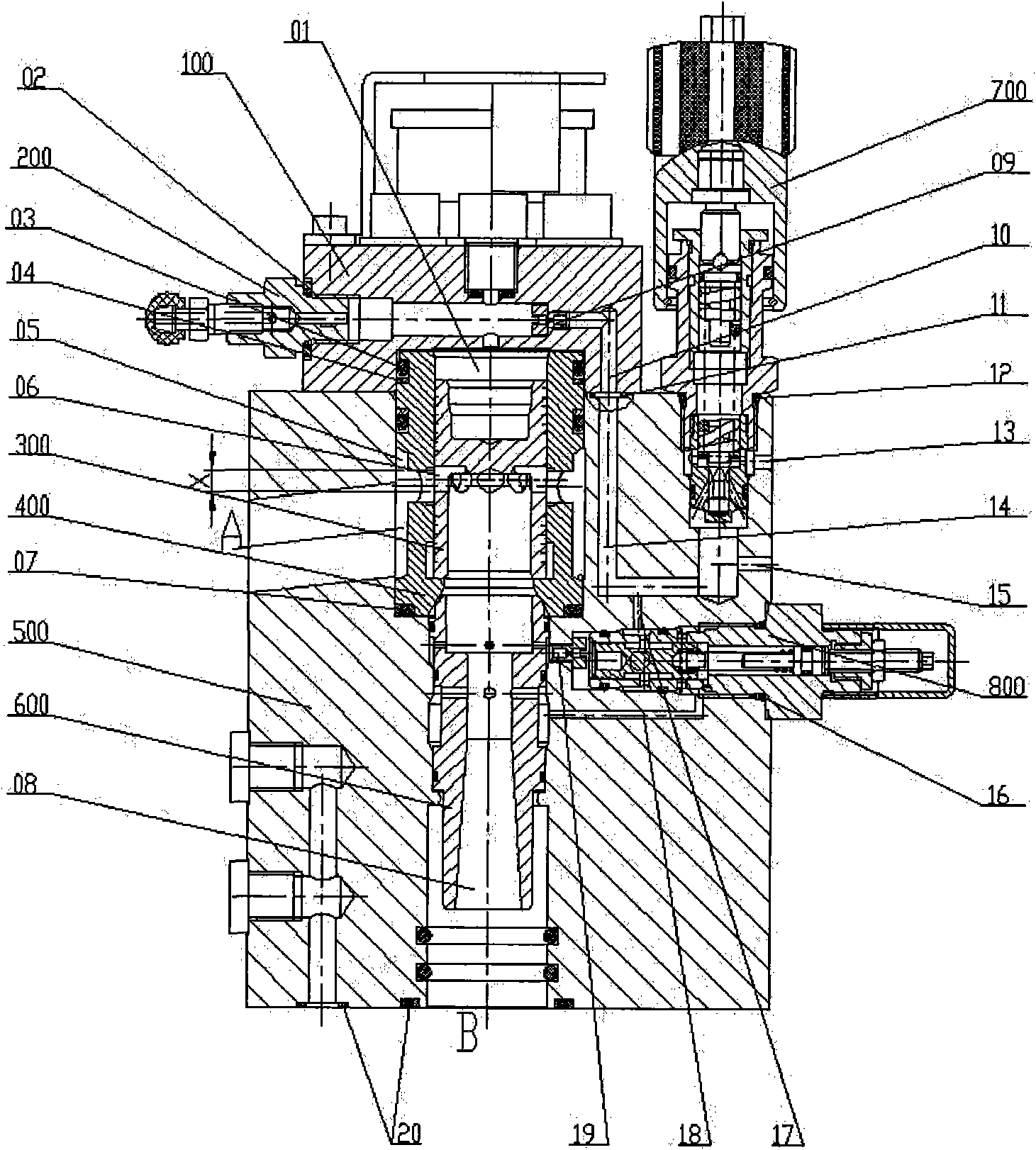
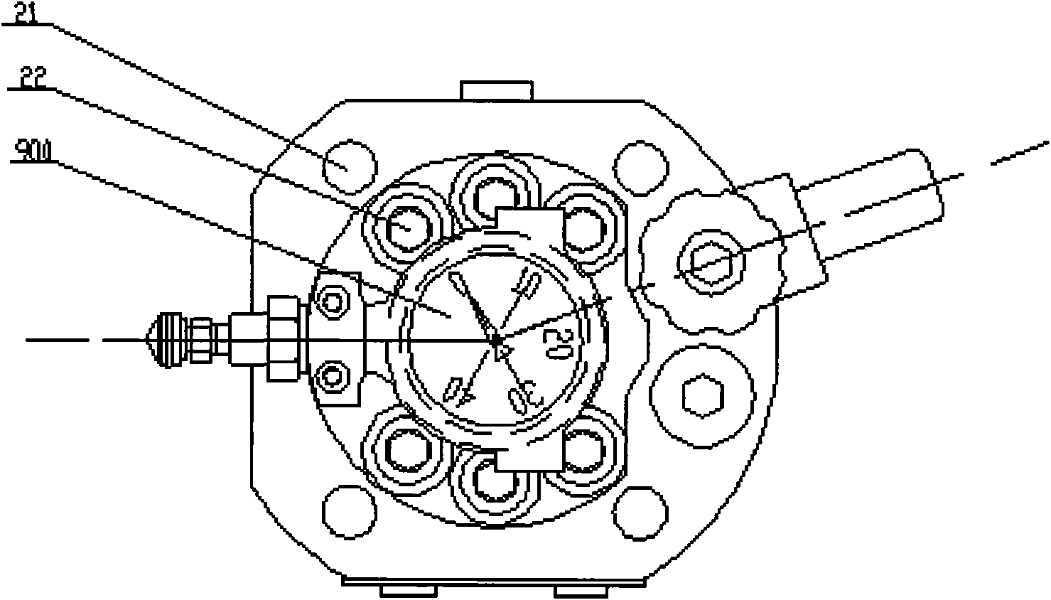
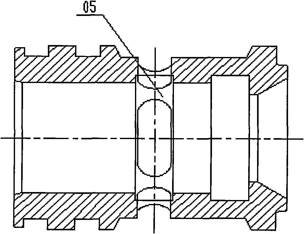
[0025] see figure 1 , figure 2 , a hydraulically controlled flow valve, including a cover plate 100, an exhaust valve 200, a main valve core 300, a main valve sleeve 400, a main valve body 500, an oil outlet sleeve 600, a relief valve insert 700, a pressure compensation insert 800, a pressure Form 900.

[0026] The outline of the main valve body 500 is a cylinder, and planes are machined in three directions of the cylinder surface to facilitate pipeline and flange connections. There is a stepped hole in the normal direction of the end face of the main valve body 500, which is the main hole. The upper end surface of the main valve body has threaded holes equidiametrically distributed along the axis of the main hole, and the screws 22 pass thr...


PUM


Abstract

The invention discloses a hydraulic control flow valve, which comprises a main valve core and a main valve body, wherein the main valve core is arranged in a main valve sleeve; the main valve sleeve is arranged in a main valve body stepped hole; an oil outlet sleeve is arranged in the main valve body stepped hole below the main valve sleeve; seal rings are arranged between the oil outlet sleeve and the main valve sleeve as well as between the oil outlet sleeve and the main valve body; a sealing member is also arranged between the main valve core and the main valve sleeve; an overflow valve insert and a pressure compensation insert are assembled on the main valve body through threads in a matching way; a cover plate is arranged above the main valve sleeve and is provided with a pressure gauge and an exhaust valve; and seal rings are arranged between the cover plate and the main valve sleeve and at the junction of the cover plate and a main valve body control oil path hole. The hydraulic control flow valve has the advantages of simple structure, convenience in processing, repair and replacement, stable and reliable speed adjustment, good sealing property, simple pipeline connection,small occupied space, convenience in observation and control of pressure and flow, small squeal during work and small jitter of the main valve core. The hydraulic control flow valve is mainly appliedto a drainage system of a liquid cargo ship and the like.

Description

technical field [0001] The invention relates to a hydraulic control valve, in particular to a hydraulic control flow valve. Background technique [0002] The hydraulic control flow valve is a valve that changes the outlet flow by adjusting and controlling the oil pressure. It is mainly used in the liquid discharge system of liquid cargo ships. At present, in China, the hydraulic control flow combination valve group composed of conventional valves is widely used to realize the control of the outlet flow change of the liquid cargo discharge system. The hydraulic control flow combination valve group has a complex structure and high processing cost; the auxiliary pipeline It takes up more space and makes the assembly more complicated. Contents of the invention [0003] In view of the above situation, the present invention provides a hydraulically controlled flow valve to solve the problems of complex structure, high processing cost, large space occupation and cumbersome assem...

Claims


Application Information

Patent Timeline
Patent Type & Authority Applications(China)
IPC IPC(8): F16K11/20F16K31/12F16K37/00F16K47/02
Inventor 袁才富瞿东朱剑根谷文平金丹何俊郑浩章米根祥沈至伟
Owner SHANGHAI LIXIN HYDRAULIC
Why Eureka
Try Eureka