Heat exchanger manufacturing method and manufacturing device

A technology for heat exchangers and manufacturing devices, which is applied in the direction of heat exchange equipment, heat exchanger types, indirect heat exchangers, etc., can solve the problems of increased maintenance costs of liner fixtures, increased time for engineering arrangement changes, etc., and achieve rapid manufacturing costs Effect

Inactive Publication Date: 2012-01-11
MITSUBISHI ELECTRIC CORP
View PDF2 Cites 2 Cited by
  • Summary
  • Abstract
  • Description
  • Claims
  • Application Information

AI Technical Summary

Problems solved by technology

Therefore, in order to manufacture heat exchangers with different fin pitches, the number of parts increases, the manufacturing process change time increases, and there are also problems such as increased maintenance costs for gasket jigs corresponding to different fin pitches.

Method used


Image

  • Heat exchanger manufacturing method and manufacturing device
  • Heat exchanger manufacturing method and manufacturing device
  • Heat exchanger manufacturing method and manufacturing device

Examples


Embodiment approach 1

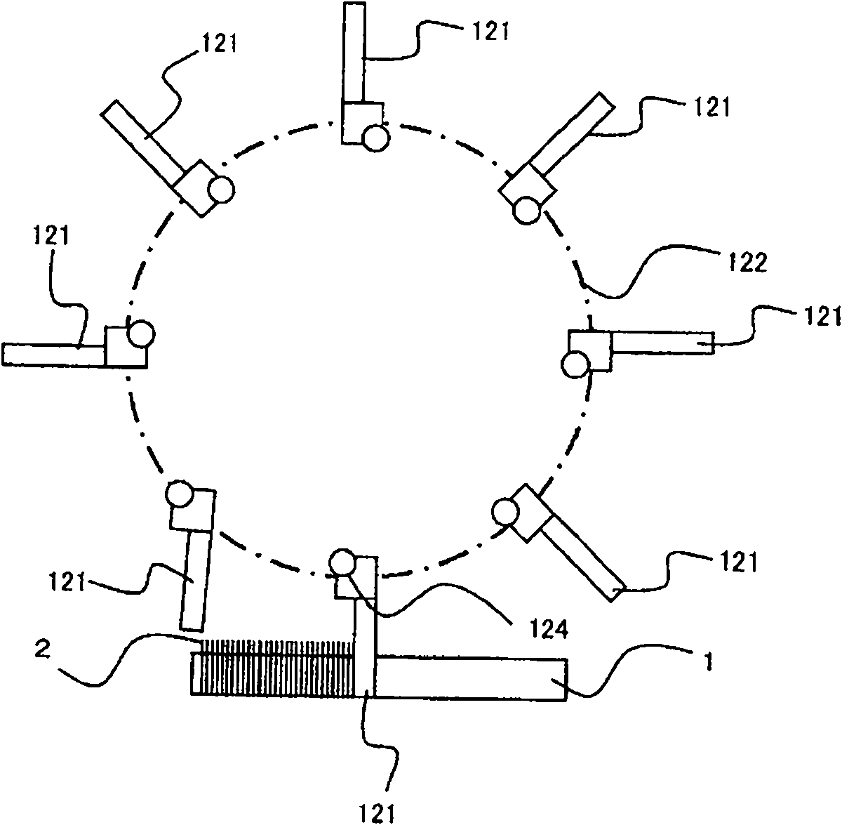
[0035] Next, the manufacturing method and manufacturing apparatus of the heat exchanger in Embodiment 1 of this invention are demonstrated. image 3 It is a schematic diagram which shows the manufacturing method and manufacturing apparatus of the heat exchanger concerning Embodiment 1 of this invention. exist image 3 , the drum 122 goes in the direction of the arrow A around the axis X, that is, in image 3 Rotate clockwise at a specified speed. On the peripheral portion of the drum 122 , eight fin holding portions 121 are provided at predetermined intervals in the circumferential direction of the drum 122 .

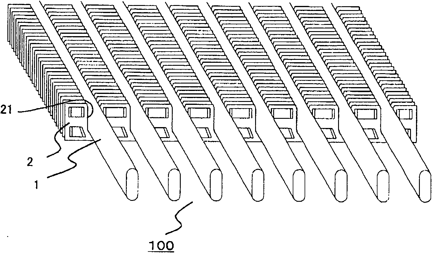
[0036] With the rotation of the drum 122, each fin holder 121 performs a circular motion centered on the axis of the shaft 126, and when it reaches the uppermost part in the vertical direction, it receives and holds a piece of fin 2, and when it reaches the lowermost part in the vertical direction , the held fins 2 are installed on the outer peripheral surface of the t...

Embodiment approach 2

[0080] In the manufacturing method and manufacturing apparatus of the heat exchanger according to Embodiment 1 above, the tubes are continuously moved at a predetermined speed in the longitudinal direction with respect to the fins to be attached, and the fins are placed on the outer peripheral surface of the moving tubes at predetermined time intervals. The fins to be installed are installed, and in the manufacturing method and manufacturing apparatus of the heat exchanger according to Embodiment 2, the tubes are intermittently moved in the longitudinal direction with respect to the fins to be installed at a pitch corresponding to a predetermined interval. When the tube stops while it is moving intermittently, the fins to be attached are attached to the outer peripheral surface of the tube. The structure of the manufacturing apparatus of the heat exchanger of this Embodiment 2 is the same as the manufacturing apparatus of the heat exchanger of Embodiment 1 mentioned above excep...

Embodiment approach 3

[0085] In the heat exchanger manufacturing apparatuses of Embodiments 1 and 2 described above, the stage on which the tubes are placed is moved, but in Embodiment 3 of the present invention, the stage is fixed and the support fins are held The way the drum side of the section moves.

[0086] Figure 11 It is an explanatory diagram showing a part of the manufacturing apparatus of the heat exchanger according to Embodiment 3 of the present invention. exist Figure 11 Among them, the pair of support parts 1741 supports the motor 128 , the coupling, the roller 122 , the fin holder 121 , the cam member 123 , the cam follower 124 , etc., and is placed on the pair of linear guides 1411 via the air cylinder 1441 . The support portion 1741 is continuously or intermittently moved on the linear guide 1411 at a predetermined speed by a motor not shown. In addition, the table portion 140 of the mounting tube 1 is fixed and configured in an immovable manner. Other configurations are the...


PUM


Abstract

The invention provides a heat exchanger manufacturing method, which results no fin deformation or fin spacing disorder and is rapid and low in cost. In the heat exchanger manufacturing method, the fins are installed in a way to make a tube move continuously or intermittently along its length direction with a set speed or with a set interval. The heat exchanger manufacturing device in the invention makes the tube inserting groove of fins held in a fin holding part and a tube imbedded. The fins are equipped on the peripheral surface of the tube. Meanwhile, the fins are sequentially installed in a way to be corresponding to the relative motion of the tube and the fin holding part. In this way, multiple fins are equipped on the peripheral surface of the tube with a set interval.

Description

technical field [0001] The present invention relates to a manufacturing method and manufacturing apparatus of a heat exchanger in which a plurality of plate-shaped fins are attached to the outer peripheral surface of a tube through which a fluid such as a refrigerant flows. Background technique [0002] As is well known, a heat exchanger used in an air conditioner or the like includes: a tube having a flat cross section as a refrigerant tube through which a fluid such as a refrigerant flows; Fins for heat exchange. Generally, such a heat exchanger is called a finned tube heat exchanger, and is simply referred to as a heat exchanger in the following description. Conventionally, as a method of manufacturing a heat exchanger, a method is used in which a plurality of plate-shaped heat exchange fins provided with insertion holes are stacked at appropriate intervals, and then the fins are flattened in cross section. The tube is inserted into the insertion hole of the tube (for e...

Claims


Application Information

Patent Timeline
Patent Type & Authority Applications(China)
IPC IPC(8): F28F1/32F28D7/16B21D53/02
Inventor 亿田宪治塚崎岳市村英男阿部武司河合孝彦木谷健一生田裕也米田典宏
Owner MITSUBISHI ELECTRIC CORP
Why Eureka
Try Eureka