Power supply transmission method of high-power wireless induction type power supplier

A power supply, wireless induction technology, applied in electrical components, circuit devices, electromagnetic wave systems, etc., can solve problems such as adjustment, high price, and safety concerns of coils that transmit power.

Active Publication Date: 2012-01-11
FU TONG TECH
View PDF6 Cites 38 Cited by
  • Summary
  • Abstract
  • Description
  • Claims
  • Application Information

AI Technical Summary

Problems solved by technology

[0005] 1. When the conventional wireless inductive power supply is in operation, the circuit board and the electronic components arranged on it will emit heat, and the coil for transmitting power will also cause safety concerns due to the heat.
[0006] 2. The circuit structure of the wireless power supply system of the conventional wireless inductive power supply includes power switching elements and resonant capacitors. At the same time, there are switching elements with high-frequency operation and high power. Even if there are switching elements, the price will be quite expensive due to the difficulty of the manufacturing process. The same is true for the resonant capacitor. turn reality into difficulty
[0007] 3. The wireless power transmitting and receiving induction coils of conventional wireless inductive power supplies need to be precisely aligned, and the power supply energy is also fixed, which cannot be adjusted according to the corresponding distance of the coils and load conditions, and the overall wireless power transmission efficiency is poor.
[0008] 4. The conventional wireless inductive power supply is designed to make the coil at the receiving end receive a voltage value greater than the target demand, and then the DC step-down integrated circuit component (DC-DCStep-DownIC) will drop the voltage to the target voltage. value, since the step-down action is also completed through switching, energy loss, interference noise and heat generation will occur during the switching process
[0009] Therefore, there are still many deficiencies in the use of the above-mentioned conventional wireless inductive power supply, and there is still a need for further improvement, which is the direction that the inventor and those engaged in this industry want to improve.

Method used


Image

  • Power supply transmission method of high-power wireless induction type power supplier
  • Power supply transmission method of high-power wireless induction type power supplier
  • Power supply transmission method of high-power wireless induction type power supplier

Examples


Embodiment Construction

[0044] In order to achieve the above-mentioned purpose and effect, the technical means and the structure adopted by the present invention are hereby illustrated in detail with respect to the preferred embodiments of the present invention. The features and functions are as follows for a complete understanding.

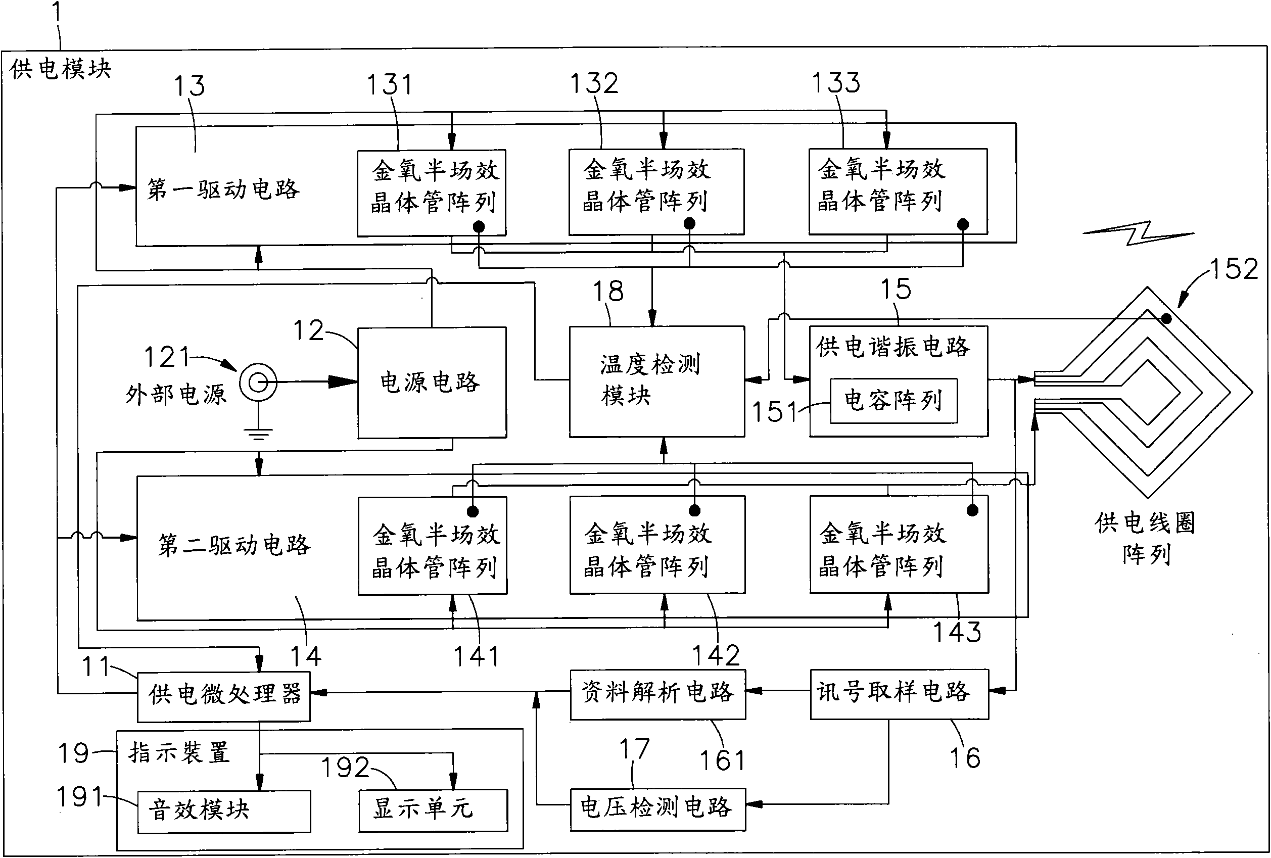
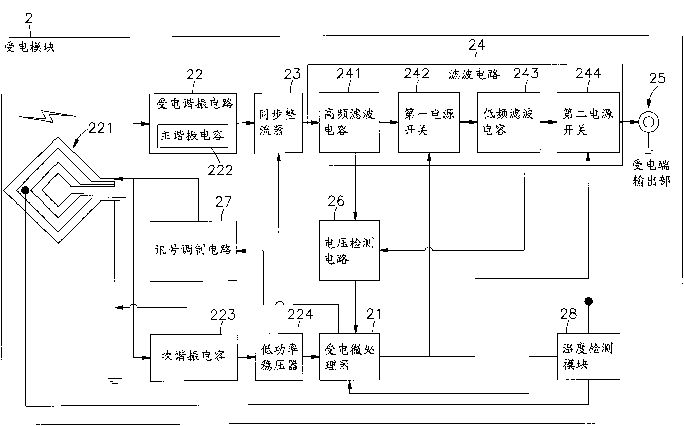
[0045] see figure 1 , 2 Shown are the block diagram of the power supply module and the block diagram of the power receiving module of the present invention, respectively. It can be clearly seen from the figure that the present invention includes a power supply module 1 and a power receiving module 2, wherein:

[0046] The power supply module 1 is provided with a power supply microprocessor 11, and related software programs and memory such as operating programs and control programs are built in the power supply microprocessor 11, and the power supply microprocessor 11 is electrically connected to an external power supply. 121 is connected to the power supply circuit 12 ...


PUM


Abstract

The invention discloses a power supply transmission method of a high-power wireless induction type power supplier, relating to a power supply module and a power receiving module. A power supply microprocessor is electrically connected with a first driving circuit and a second driving circuit which are respectively provided with two or more than two groups of metal-oxide semi-field-effect transistor arrays connected in parallel; the first driving circuit and the second driving circuit are electrically connected with a power supply resonance circuit with a capacitance array; and the power supply resonance circuit is electrically connected with a power supply coil array, so that the electromagnetic wave energy can be outputted to the power receiving module through frequency conversion and driving power adjustment, and through a main resonance capacitor and a secondary resonance capacitor connected with the power receiving coil array in parallel, and a synchronous rectifier connected withthe main resonance capacitor electrically, the direct-current power is outputted to outside by a high-frequency filter capacitor, a first power supply switch, a low-frequency filter capacitor and a second power supply switch in a filter circuit in sequence. In the power supply transmission method, due to the design of low impedance of a power transmission loop, not only can the high-power wireless power transmission be realized, but also the output power can be adjusted according to the load condition.

Description

technical field [0001] The present invention provides a power transmission method for a high-power wireless inductive power supply, especially that the power supply module can use frequency conversion technology and multiple array structures to adjust the output power in response to the power level, and output electromagnetic wave energy to the power receiving module safely and efficiently. Efficient wireless power supply. Background technique [0002] In today's era of electronic technology and the endlessness of the Internet, various digital products are flooding our lives, such as digital cameras, mobile phones, multimedia players (MP3 or MP4, MP5 players), etc. Portable electronic devices, and the portable electronic devices are designed towards the concepts of lightness, thinness, shortness and smallness. [0003] However, if the portable electronic device is to be carried with you, the first thing that must be solved is the problem of power consumption, and the most c...

Claims


Application Information

Patent Timeline
Patent Type & Authority Applications(China)
IPC IPC(8): H02J17/00H02J50/12
Inventor 蔡明球詹其哲
Owner FU TONG TECH
Why Eureka
Try Eureka