Motor rotor system

A motor rotor and rotor core technology, applied in the direction of electric components, electrical components, electromechanical devices, etc., can solve the problems of reduced efficiency, low precision, and large differences in the overall performance of the motor, and achieve low noise and vibration, stable operation, and excellent structure. compact effect

Active Publication Date: 2015-04-29
ZHONGSHAN BROAD OCEAN MOTOR MFG
View PDF5 Cites 0 Cited by
  • Summary
  • Abstract
  • Description
  • Claims
  • Application Information

AI Technical Summary

Problems solved by technology

[0002] At present, brushless DC motors use position sensors (Hall elements) to measure the position of the rotor so that the motor controller can issue commutation commands in time. Now there is a sine wave control method with a position sensor. In this control mode, the main rotor of the motor The magnetic field uses a strong magnetic field, and the control drive signal has higher requirements for the consistency of the motor's back EMF and the Hall output signal. If the consistency is not good, it will cause the program used for one motor to be used on another. Abnormal phenomenon occurs, the noise and vibration of the motor will increase, the efficiency will decrease, and the unique advantages of the sine wave motor will be lost. In severe cases, the motor will vibrate and lose steps
At present, the rotor system still has the following problems: 1. Add a first-stage induction magnetic ring after the main magnetic field of the motor. The problem is that the relative position between the main magnetic field and the induced magnetic field is not easy to control, and the accuracy is not high, which affects the measurement accuracy; 2. Charging Enterprises with better magnetic technology use the method of magnetizing the main magnetic field and the induced magnetic field together. This method is suitable for magnetic materials with low magnetic properties such as ferrite or bonded NdFeB, and is not suitable for strong magnetic materials such as sintered NdFeB. Material, because the process does not allow; 3. Add an adjustable Hall component behind the motor end cover, detect the relative position of the Hall signal and the back EMF waveform by dragging the back EMF, and then adjust the fine-tuning Hall component to Realize the relative positional relationship between the required main magnetic field and the induced magnetic field. This method is not good in manufacturability, and the overall accuracy is not high. The overall performance of the motor varies greatly, and installation is troublesome.

Method used


Image

  • Motor rotor system
  • Motor rotor system
  • Motor rotor system

Examples


Embodiment Construction

[0024] The present invention will be described in further detail below through specific embodiments and in conjunction with the accompanying drawings.

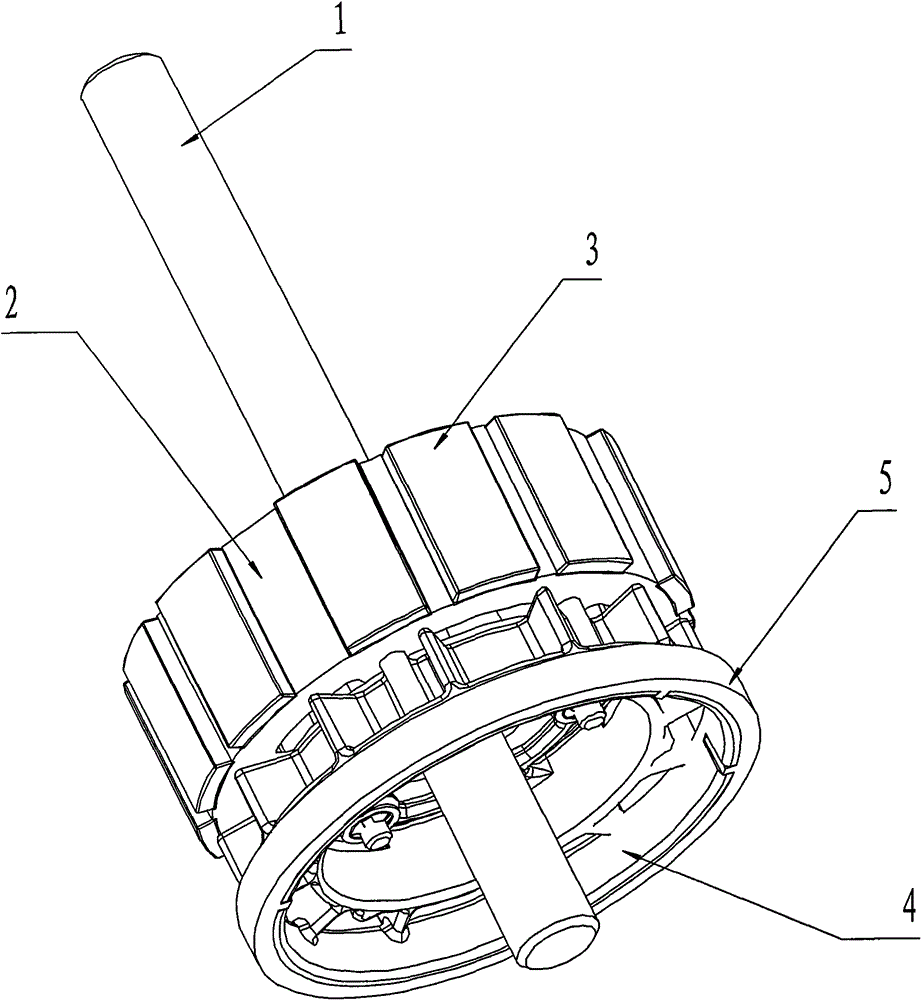
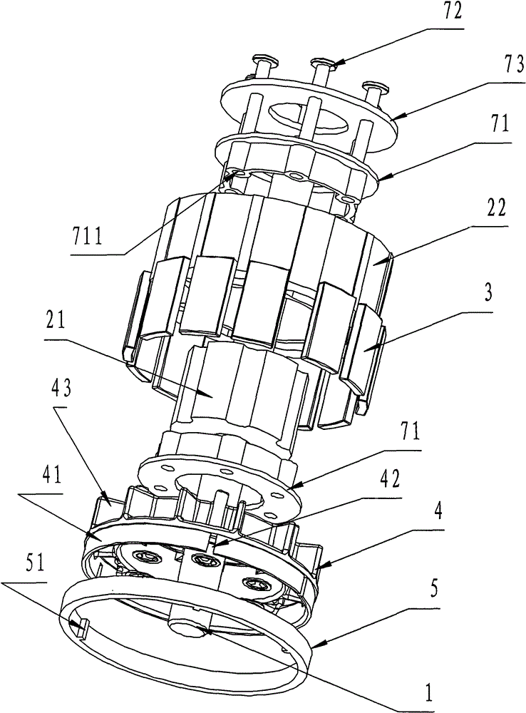
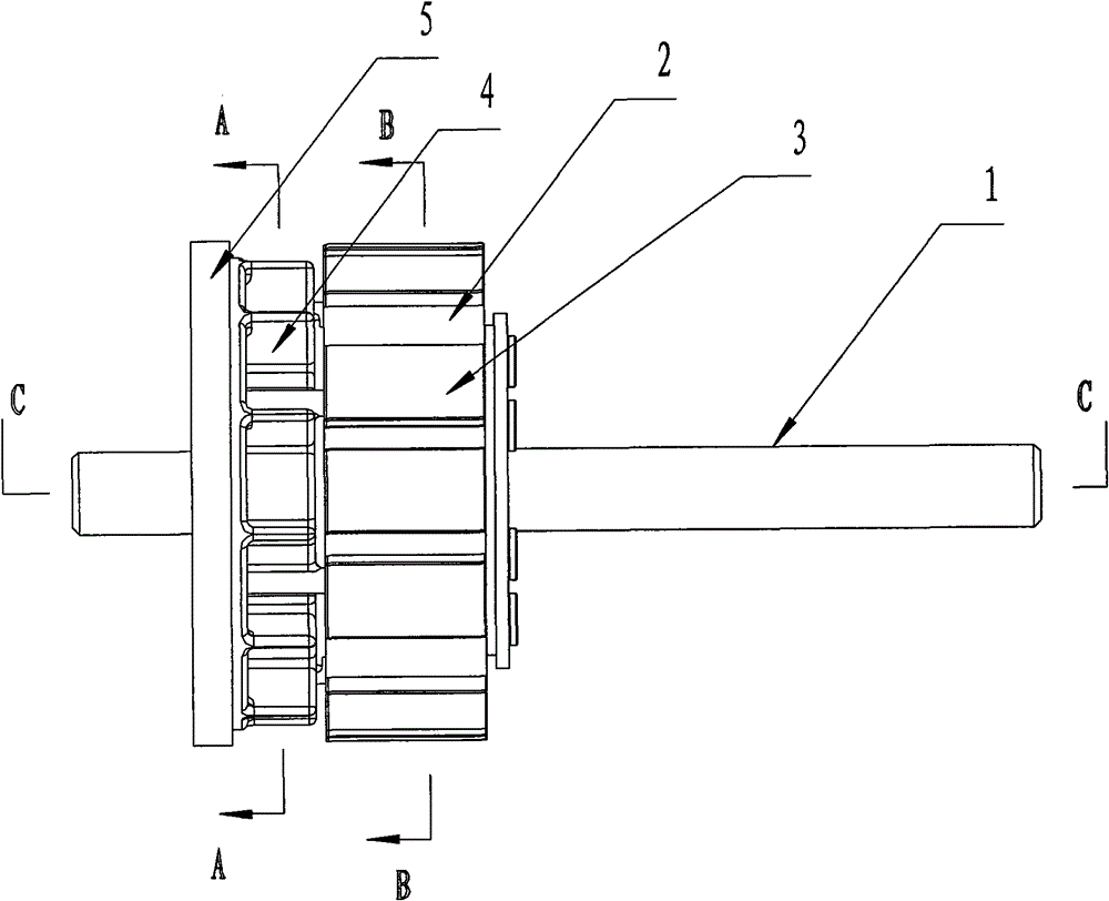
[0025] Such as figure 1 , figure 2 , image 3 , Figure 4, Figure 5, Figure 6, Figure 7 , Figure 8 , Figure 9 As shown, a motor rotor system includes a rotating shaft 1, a rotor core 2 installed on the rotating shaft 1, a permanent magnet 3 installed on the rotor core 2, a magnetic ring bracket 4 and a magnetic ring 5, and the magnetic ring 5 is set on the On the magnetic ring support 4, the magnetic ring support 4 is located at one end of the rotor core 2 and is connected to the end face of the rotor core 2 for installation. The positioning protrusion 51 on the wall is fitted with the positioning groove 42 so that the magnetic ring 4 is installed on the outside of the magnetic ring bracket 3 . The magnetic ring bracket 4 is provided with an annular inner ring 45 , a plurality of cooling fan blades 43 protrude from th...


PUM


Abstract

The invention discloses a motor rotor system, which comprises a revolving shaft (1), a rotor core (2), a permanent magnet (3), a magnet ring support (4) and a magnet ring (5), wherein the rotor core is the arranged on the revolving shaft (1); the permanent magnet (3), the magnet ring support (4) and the magnet ring (5) are arranged on the rotor core (2); the magnet ring (5) is sleeved on the magnet ring support (4); and the magnet ring support (4) is positioned on one side of the rotor core (2) and connected with an end face of the rotor core (2). The motor rotor system has the advantages that: the main field corresponds to the induced field of the rotor accurately; the motor rotor system is high in consistency, is suitable for batch production, has a simple structure, and is convenient to install; and sine wave driving control mode with a position sensor can be implemented.

Description

Technical field: [0001] The invention relates to a motor rotor system. Background technique: [0002] At present, brushless DC motors use position sensors (Hall elements) to measure the position of the rotor so that the motor controller can issue commutation commands in time. Now there is a sine wave control method with a position sensor. In this control mode, the main rotor of the motor The magnetic field uses a strong magnetic field, and the control drive signal has higher requirements for the consistency of the motor's back EMF and the Hall output signal. If the consistency is not good, it will cause the program used for one motor to be used on another. In case of abnormal phenomenon, the noise and vibration of the motor will increase, the efficiency will decrease, and the unique advantages of the sine wave motor will be lost. In severe cases, the motor will vibrate and lose steps. At present, the rotor system still has the following problems: 1. Add a first-stage induct...

Claims


Application Information

Patent Timeline
Patent Type & Authority Patents(China)
IPC IPC(8): H02K29/00H02K1/28H02K1/22H02K11/00H02K11/20
Inventor 潘明攀
Owner ZHONGSHAN BROAD OCEAN MOTOR MFG
Why Eureka
Try Eureka