
Clock synchronization device and method

A clock synchronization and clock technology, which is applied in the field of communication, can solve the problems that the clock synchronization device cannot output the clock phase guarantee, the clock signal phase is uncontrollable, the clock system index is not good, etc., and achieves a flexible structure, simple control steps, and easy control. Effect

Inactive Publication Date: 2012-01-11
DATANG MOBILE COMM EQUIP CO LTD
View PDF5 Cites 22 Cited by
  • Summary
  • Abstract
  • Description
  • Claims
  • Application Information

AI Technical Summary

Problems solved by technology

[0012] The above-mentioned clock synchronization device cannot guarantee the phase of the output clock, because after the device passes through the frequency synthesizer and the clock drive circuit, the output clock signal will have a phase change, and the change value is unknown
Even if it is guaranteed that f0 and f1 are in the same phase, it has no practical significance
And the two-stage phase-locked loop is independent, the jitter of the previous stage will continue to be transmitted to the next stage, thus affecting the system indicators
Therefore, the disadvantages of the above-mentioned clock synchronization device are: the phase of the final output clock signal is uncontrollable and the clock system index is not good

Method used


Image

  • Clock synchronization device and method
  • Clock synchronization device and method
  • Clock synchronization device and method

Examples


Embodiment Construction

[0034] The clock synchronization device and method provided by the present invention will be described in more detail below with reference to the accompanying drawings and embodiments.

[0035] The purpose of the present invention is to provide a new clock synchronization device and method, eliminate the jitter and drift generated in the current reference source, and provide a high-performance clock synchronization system for various communication systems. Of course, it can also be applied to phase-locked other fields.

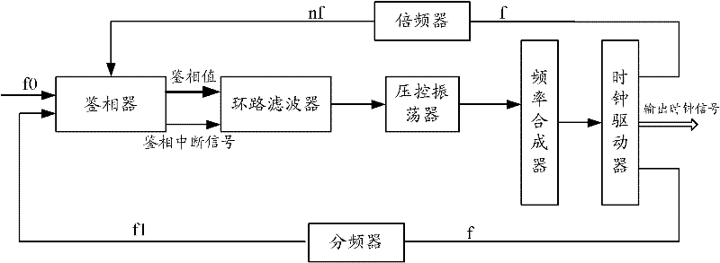
[0036] The clock synchronization device provided by the embodiment of the present invention, such as figure 2 As shown, it includes a phase detector, a loop filter, a voltage-controlled oscillator, a frequency synthesizer and a clock driver connected in sequence, where,

[0037] The clock signal f output by the clock driver is fed back to the input terminal of the phase detector after frequency division by the frequency divider, according to figure 2 , the...


PUM


Abstract

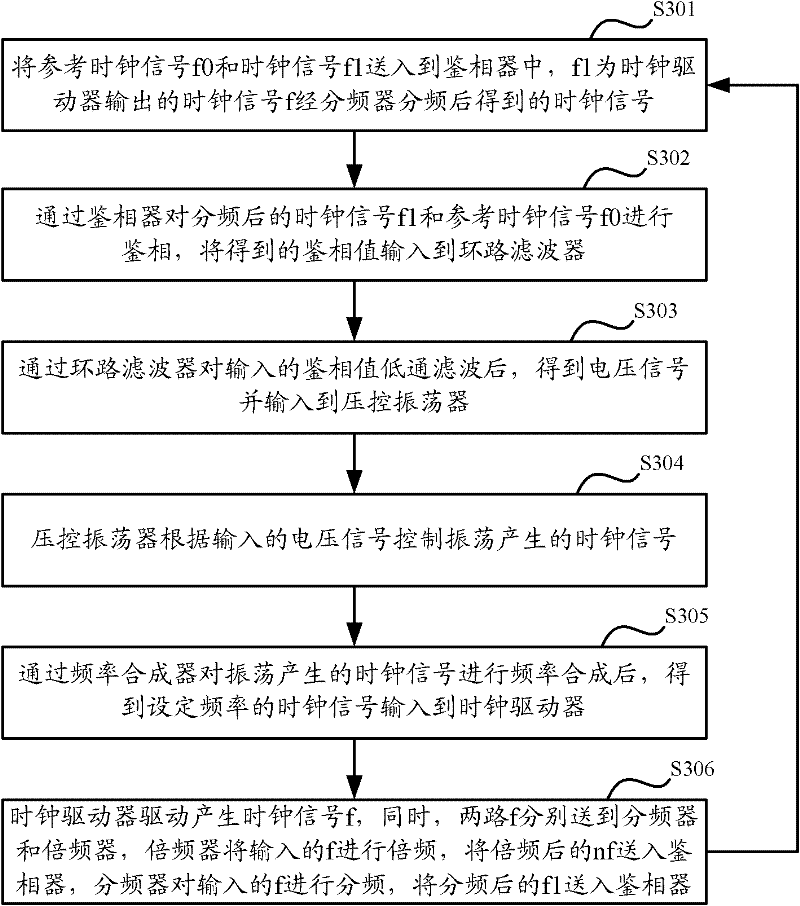
The invention discloses a clock synchronization device and method. The device comprises a phase discriminator, a loop filter, a voltage-controlled oscillator, a frequency synthesizer and a clock driver in the sequential connection, wherein clock signals output by the clock driver are fed back to an input end of the phase discriminator after being subjected to frequency division by a frequency divider; phase discrimination is carried out on the clock signals which is subjected to the frequency division and reference clock signals by the phase discriminator, and the obtained phase discrimination value is input to the loop filter; after the input phase discrimination value is subjected to low pass filtering by the loop filter, voltage signals are obtained and then input to the voltage-controlled oscillator, and the voltage-controlled oscillator controls the clock signals generated by oscillation according to the input voltage signals; and after the frequency synthesizer performs the frequency synthesis on the clock signals generated by the oscillation, the obtained clock signals with set frequencies are input into the clock driver, and the clock driver drives the clock signals to generate the required clock signals. According to the invention, the phase position of a clock can be controlled and output accurately, and the system clock performance is improved.

Description

technical field [0001] The invention relates to clock technology in the field of communication, in particular to a clock synchronization device and method. Background technique [0002] For the communication network, it needs to provide a variety of different application services, from common services to intelligent value-added services, from voice to data, image and other comprehensive services. The coexistence of multiple services makes the clock problem of the system more and more important. [0003] A stable clock signal is the basis for the normal operation of various devices in the communication network. If there is no good clock signal, digital information will inevitably have errors and slippages during the transmission process, resulting in a decline in communication quality. Depending on the business, it has different degrees of impact. For example, there will be a clicking sound for voice calls; fax services will cause incomplete information; data service packet ...

Claims


Application Information

Patent Timeline
IPC IPC(8): H04L7/00H04L7/033
Inventor 何宇东
Owner DATANG MOBILE COMM EQUIP CO LTD
Learn More