Fuel cell system comprising at least one fuel cell

A fuel cell system and fuel cell technology, applied in the direction of fuel cells, fuel cell additives, circuits, etc., can solve the problems of insufficient cooling area, ineffective use, poor performance, etc., and achieve the effect of preventing environmental diffusion

Inactive Publication Date: 2012-01-11
DAIMLER AG
View PDF5 Cites 3 Cited by
  • Summary
  • Abstract
  • Description
  • Claims
  • Application Information

AI Technical Summary

Problems solved by technology

[0004] This mode of operation certainly represents a corresponding advantage for a cold start of such a fuel cell system, but for normal operation it is very critical to convey this waste heat to the cooling water because, for example, there is enough energy available on the vehicle The cooling area used to cool the fuel cell is insufficient or poor
Furthermore, in the design of US 2005 / 0019633 A1, the waste heat generated in the area of ​​the catalytic burner cannot be used effectively except in the case of cold start

Method used


Image

  • Fuel cell system comprising at least one fuel cell
  • Fuel cell system comprising at least one fuel cell
  • Fuel cell system comprising at least one fuel cell

Examples


Embodiment Construction

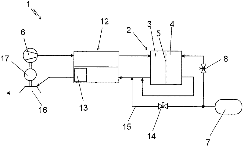
[0019] The illustrations in the following figures show, in very simplified illustrations, only the components necessary to understand the rather complex fuel cell system of the present invention. It is therefore self-evident for the fuel cell system that further components, such as cooling circuits etc., are also provided within the fuel cell system, although they are also not considered in the figures shown below.

[0020] figure 1 A fuel cell system 1 comprising a fuel cell 2 is now shown. The fuel cell 2 thus comprises a stack of individual cells constructed in a conventional manner. A cathode region 3 and an anode region 4 are formed in the fuel cell 2 , and these regions are separated from each other by a PE membrane 5 in the present embodiment. exist figure 1 In the illustrated embodiment, the intake air flow is delivered to the cathode zone 3 by means of a compressor 6 . The compressor 6 can thus be designed, for example, as a screw compressor or as a flow compresso...


PUM


Abstract

A fuel cell system (1) comprises at least one fuel cell (2) that has a cathode region (3) and an anode region (4). The fuel cell system further comprises an exchanging device (12), through which an intake air stream flowing to the cathode region (3) and a used air stream discharged from the cathode region (3) flow. In said exchanging device (12), heat is transferred from the intake air stream to the used air stream, and steam is simultaneously transferred from the used air stream to the intake air stream. The fuel cell system also comprises a compressor (6) which can be driven at least in an assisting manner by a turbine (16). Said turbine (16) is disposed downstream of the exchanging device (12) and is penetrated by used air. Furthermore, a catalytic material, to which a fuel-containing gas can be fed, is disposed upstream of the turbine (16). According to the invention, the catalytic material (13) is integrated into the exchanging device (12) at the used air end, to which an exhaust gas from the anode region (4) can be fed.

Description

technical field [0001] The invention relates to a fuel cell system comprising at least one fuel cell according to the type defined in detail in the preamble of claim 1 . Background technique [0002] DE 102007003144A1 describes a conventional fuel cell system. This fuel cell system includes a displacement device that combines the two functions of "cooling" and "humidification". This displacing device, referred to in this document as a functional unit, allows material flow from the exhaust air of the fuel cell to the intake air of the fuel cell, while at the same time the flow from the intake air heated by the compression device to the comparative Heat exchange with cool discharge air. DE 10 2007 003 144 A1 thus additionally discloses an arrangement in which the air supply of the fuel cell system takes place via a compressor, which can be driven on the one hand by a turbine and / or on the other hand by an electric motor. This structure, which is generally known in fuel cell...

Claims


Application Information

Patent Timeline
Patent Type & Authority Applications(China)
IPC IPC(8): H01M8/04H01M8/06
CPCY02E60/50H01M8/04141H01M8/04097H01M8/0662H01M8/04111
Inventor G·康拉德F·施特克
Owner DAIMLER AG
Why Eureka
Try Eureka