Electron beam welding method for large-thickness diaphragms of steam turbines
A technology of electron beam welding and large thickness, applied in electron beam welding equipment, welding equipment, metal processing equipment, etc., can solve the problems of difficult to guarantee welding quality, difficult welding seam forming, and difficult welding seam cleaning, and improve welding quality. , the effect of poor working conditions and reducing the probability of repair
- Summary
- Abstract
- Description
- Claims
- Application Information
AI Technical Summary
Problems solved by technology
Method used
Image

Examples
specific Embodiment approach 1
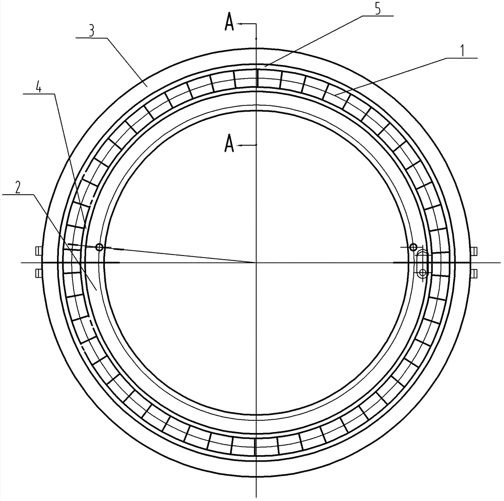
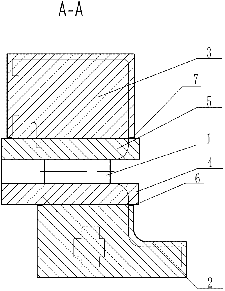
[0015] Specific implementation mode one: combine figure 1 and figure 2 Describe this embodiment, the method of this embodiment comprises the following steps:
[0016] Step 1. Marking line: draw the horizontal middle surface line on the inner plate body 2, outer plate body 3, inner peripheral belt 4, outer belt 5 and tooling (according to the design requirements), and draw a horizontal line on the guide vane 1 at the same time. The middle surface line (marked line should be clear) and drill holes in the corresponding position for observation; (the corresponding position refers to the drawn horizontal middle surface line, punching holes on the line, so that the traces are clear, and it is convenient for electron beam welding Observe, otherwise the scribe line will not be seen when welding)
[0017] Step 2. Assembly: According to the line drawn in step 1, assemble the cascade (the cascade is composed of guide vane 1, inner band 4, and outer band 5, and assemble and weld guide ...
specific Embodiment approach 2
[0026] Specific implementation mode two: combination figure 1 Describe this embodiment, in step 6 of this embodiment, the accelerating voltage during preheating is 55KV, welding speed is 300mm / min, electron beam current is 60mA, focusing current is 1550mA, and the scanning swing of electron beam in X direction is 1.8, the scanning swing of the electron beam in the Y direction is 2.0, and the gun distance is 320mm;
[0027] The accelerating voltage during sealing welding is 55KV, the welding speed is 250mm / min, the electron beam current is 100mA, the focusing current is 1850mA, the scanning swing of the electron beam in the X direction is 1.8, and the scanning swing of the electron beam in the Y direction is 2.0 , the gun distance is 320mm;
[0028] When welding the inner circle, the accelerating voltage is 55KV, the welding speed is 150mm / min, the electron beam current is 380mA, the focusing current is 1800mA, the scanning swing of the electron beam in the X direction is 0, a...
specific Embodiment approach 3
[0032]Specific embodiment three: in step six of the present embodiment, the accelerating voltage during preheating is 55KV, the welding speed is 400mm / min, the electron beam current is 80mA, the focusing current is 1550mA, and the scanning swing of the electron beam in the X direction is 3.6, the scanning swing of the electron beam in the Y direction is 4.0, and the gun distance is 320mm;
[0033] The accelerating voltage during sealing welding is 55KV, the welding speed is 300mm / min, the electron beam current is 190mA, the focusing current is 1850mA, the scanning swing of the electron beam in the X direction is 1.8, and the scanning swing of the electron beam in the Y direction is 2.0 , the gun distance is 320mm;
[0034] When welding the inner circle, the accelerating voltage is 55KV, the welding speed is 150mm / min, the electron beam current is 380mA, the focusing current is 1800mA, the scanning swing of the electron beam in the X direction is 0, and the scanning swing of th...
PUM
| Property | Measurement | Unit |
|---|---|---|
| thickness | aaaaa | aaaaa |
Abstract
Description
Claims
Application Information
 - R&D
- Intellectual Property
- Life Sciences
- Materials
- Tech Scout
- Unparalleled Data Quality
- Higher Quality Content
- 60% Fewer Hallucinations
Browse by: Latest US Patents, China's latest patents, Technical Efficacy Thesaurus, Application Domain, Technology Topic, Popular Technical Reports.
© 2025 PatSnap. All rights reserved.Legal|Privacy policy|Modern Slavery Act Transparency Statement|Sitemap|About US| Contact US: help@patsnap.com