Ejector capable of directly releasing energy by using superconducting magnet

A technology of superconducting magnets and catapults, which is applied in the direction of launching/dragging transmission devices, etc., can solve problems such as no direct drive catapult system solutions, and achieve improved energy utilization efficiency, simplified energy conversion process, and strong electromagnetic driving force Effect

Inactive Publication Date: 2012-01-18
吴春俐
View PDF4 Cites 27 Cited by
  • Summary
  • Abstract
  • Description
  • Claims
  • Application Information

AI Technical Summary

Problems solved by technology

There is also a design scheme using a superconducting energy storage magnet as a pulse power supply, but there is no scheme that uses the energy release process of a superconducting energy storage magnet to directly drive the ejection system

Method used


Image

  • Ejector capable of directly releasing energy by using superconducting magnet
  • Ejector capable of directly releasing energy by using superconducting magnet
  • Ejector capable of directly releasing energy by using superconducting magnet

Examples


Embodiment Construction

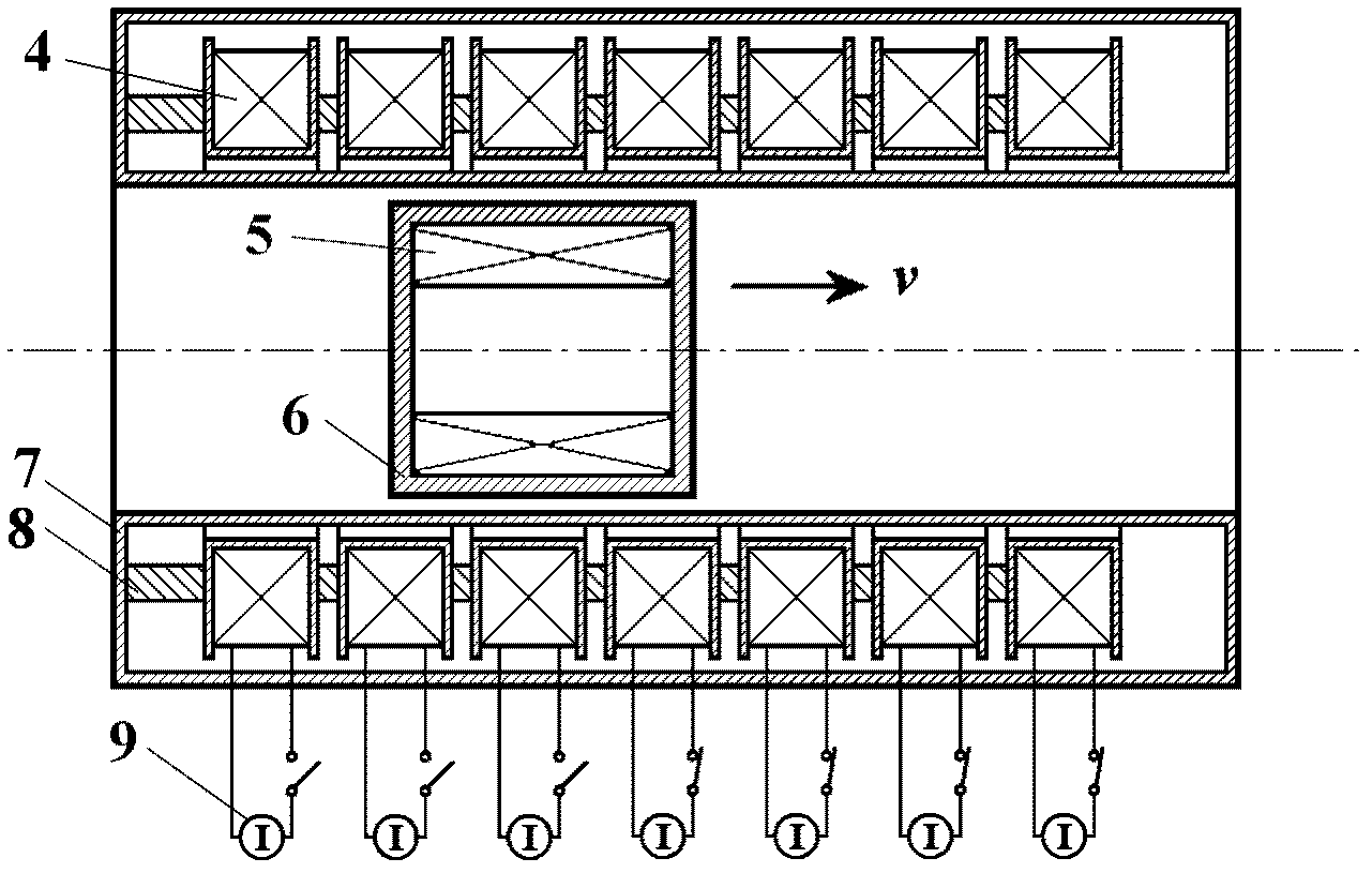
[0022] The present invention is described in detail in combination with specific embodiments and accompanying drawings.

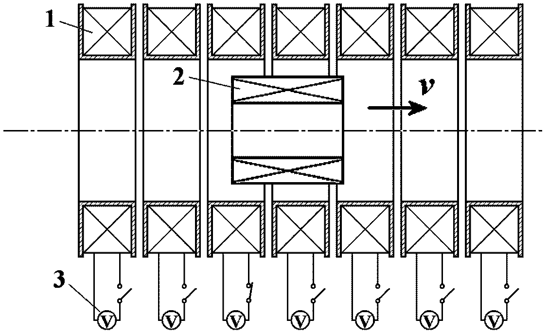
[0023] In the present invention, as figure 2 The superconducting electromagnetic catapult shown. The multistage superconducting driving coils 4 are coaxially arranged in a circular tube shape. Because the force in the working process is very large, there must be strong support between the superconducting drive coils 4 at all levels. Because the superconducting working environment requires low temperature, the outer surface of the superconducting drive coil 4 is surrounded by a shell with relatively high heat insulation requirements—a cryogenic container 7 . A strong supporting structure 8 must also be adopted between the cryogenic container 7 and the superconducting driving coil 4 . Cryogenic liquids such as liquid nitrogen and liquid helium can be used inside the cryogenic container 7 , and a conduction cooling form of a refrigerator can also be used. ...


PUM


Abstract

The invention provides an ejector capable of directly releasing energy by using a superconducting magnet, belonging to the field of a superconducting technology. The ejector comprises a low-temperature container shell, superconducting drive coils, an armature, a superconducting power supply, a supporting frame and an armature low-temperature container; the low-temperature container shell is a hollow and sealed container and multiple levels of superconducting drive coils are installed on the inner wall of the low-temperature container shell; and the ejection coil is distributed on the axis in a pipeline which is composed of the superconducting drive coils and the low-temperature container shell. The armature can flexibly move on the axis; each level of the superconducting drive coil is equipped with one superconducting power supply or several levels of the superconducting drive coils are equipped with one power supply. The ejector capable of directly releasing energy by using the superconducting magnet has the advantages that: the superconducting energy storage property is directly utilized and the superconducting power supply with smaller power can be used for charging a magnetic field to the superconducting drive coils, so that the electromagnetic drive force is stronger than that of the traditional design scheme which utilizes an impulse power supply to charge the fixed drive coil and is repelled with the armature. In the invention, the conversion process of the energy is simplified and the utilization efficiency of the energy is improved.

Description

technical field [0001] The invention belongs to the field of superconducting engineering technology, in particular to a superconducting magnet direct release energy catapult. Background technique [0002] Catapults are mainly used in the take-off process of aircraft, and can also be used in high-speed acceleration systems for other large-mass objects. In the past, the electromagnetic ejection system used the pulse power supply to work, and the power supply was separated from the driving process, and the system efficiency was low. Due to the high technical requirements of high-power pulse power supply, mature electromagnetic ejection systems are very rare. There is also a design scheme using superconducting energy storage magnets as a pulse power supply, but there is no scheme that uses the energy release process of superconducting energy storage magnets to directly drive the ejection system. A "coil gun" is a launch tube composed of a series of fixed drive coils, inside (o...

Claims


Application Information

Patent Timeline
Patent Type & Authority Applications(China)
IPC IPC(8): B64F1/06
Inventor 吴春俐白质明
Owner 吴春俐
Why Eureka
Try Eureka