Safe passage device used in tunneling construction collapse

A technology for safe passage and tunnel construction, which is applied in safety devices, earthwork drilling, mining equipment, etc., can solve the problems of complex construction, large space occupation, and high cost, and achieve universal practical value, small space occupation, and small construction interference Effect

Inactive Publication Date: 2012-01-18
建发合诚工程咨询股份有限公司
9 Cites 1 Cited by

AI-Extracted Technical Summary

Problems solved by technology

Due to the unsatisfactory effect of the current tunnel construction landslide rescue measures and the high cost, the tunnel construction landslide rescue is still a worldwide problem
At present, there are also rel...

Abstract

The invention provides a safe passage device used in a tunneling construction collapse, relating to a safe passage device used in a tunneling construction collapse which is convenient to escape. The device has the advantages of small occupied space, low cost, easiness in self construction and extremely low tunneling construction interferences. The device is provided with annular lifesaving tubes with hollow sealed tube walls and a high-pressure air supply device. When the device is used, the annular lifesaving tubes are paved at the left or right side in the tunnel directly until the annular lifesaving tubes are paved at positions close to a working face from positions near a secondary lining in the longitudinal direction of the tunnel. When the collapse happens in the tunneling construction, the high-pressure air supply device injects high-pressure gases into the annular lifesaving tubes, so that the annular lifesaving tubes expand into emergency rescue safe passages like swimming lifebelts. Workers can use the expanded annular lifesaving tubes to pass through a collapsed zone for escape, thus reaching the purpose of rescuing trapped persons.

Application Domain

Safety equipments

Technology Topic

Tunnel engineeringTunnel construction +5

Image

  • Safe passage device used in tunneling construction collapse
  • Safe passage device used in tunneling construction collapse
  • Safe passage device used in tunneling construction collapse

Examples

  • Experimental program(1)

Example Embodiment

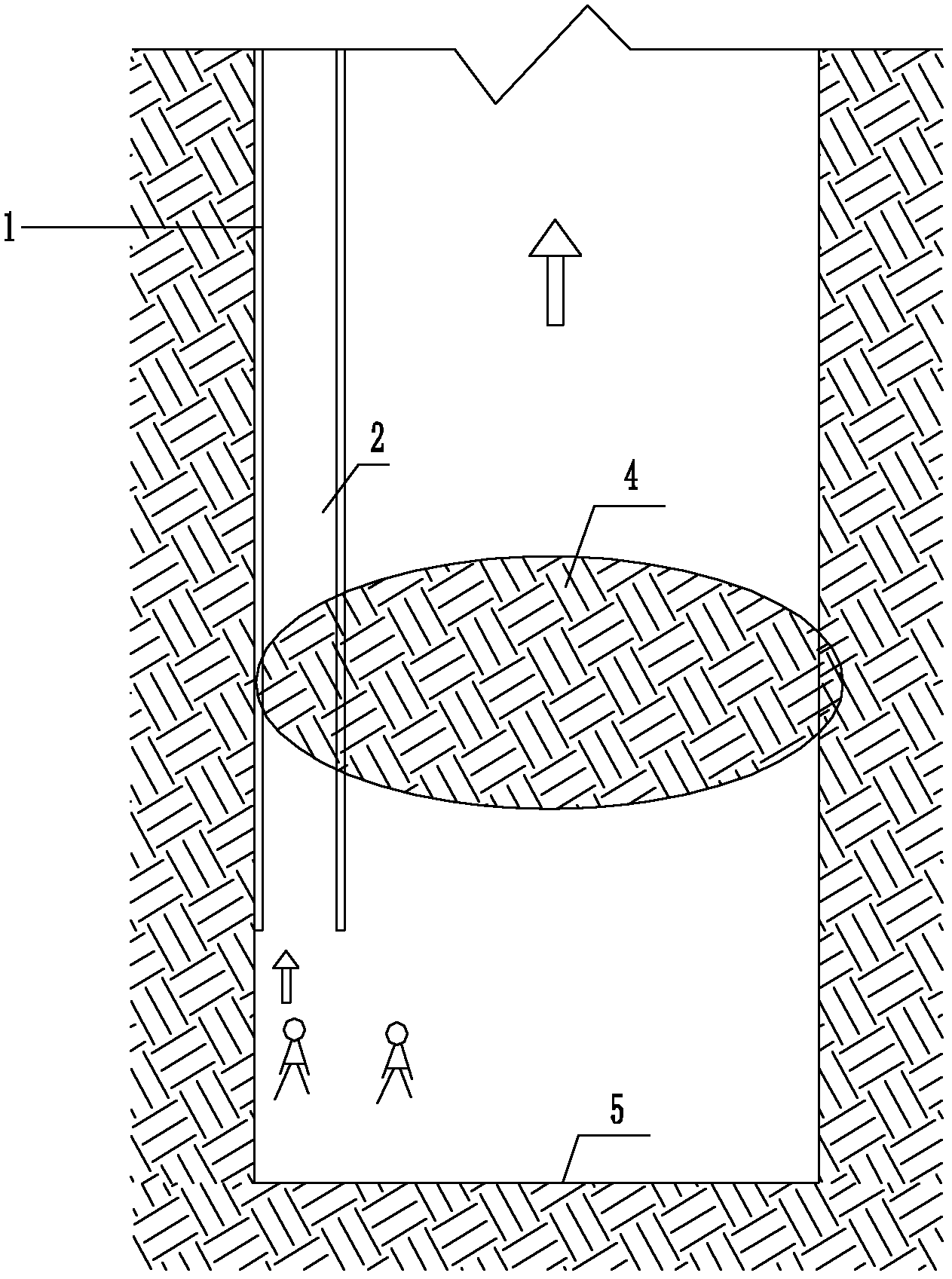
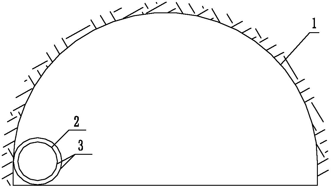
[0013] see figure 1 and 2 , the embodiment of the present invention is provided with an annular life-saving pipe 2 and a high-pressure air supply device ( figure 1 and 2 not shown). The pipe wall 3 of the annular lifesaving pipe 2 is a hollow sealed pipe wall, and the cross-sectional shape of the annular lifesaving pipe 2 is the shape of a swimming lifebuoy. An inlet and outlet valve ( figure 1 and 2 (not shown in the figure), the inlet and outlet valves are connected to the high-pressure gas outlet of the high-pressure gas supply device, and the wall material of the hollow sealing tube wall of the annular life-saving tube 2 is composed of 5 layers of rubber layers and at least 3 layers of carbon fiber layers. The composite material, the inner and outer surfaces of the hollow sealing tube wall are both rubber layers, and the carbon fiber layer is arranged between the two rubber layers. The annular life-saving pipe 2 is laid from the vicinity of the secondary lining 1 to the vicinity of the tunnel face 5 along the longitudinal direction of the tunnel. The inner diameter of the annular life-saving tube is 1.0m, and the outer diameter may be 1.2m. The high-pressure air supply device adopts the existing high-pressure air pump and other supporting devices ( figure 1 and 2 not shown). Reference numeral 4 denotes a collapse section area. Arrows indicate escape directions.

PUM

PropertyMeasurementUnit
The inside diameter of1.0m
Outer diameter1.2m

Description & Claims & Application Information

We can also present the details of the Description, Claims and Application information to help users get a comprehensive understanding of the technical details of the patent, such as background art, summary of invention, brief description of drawings, description of embodiments, and other original content. On the other hand, users can also determine the specific scope of protection of the technology through the list of claims; as well as understand the changes in the life cycle of the technology with the presentation of the patent timeline. Login to view more.

Similar technology patents

Body condition measuring device

InactiveUS20050234351A1simple structure
Owner:DENSO CORP

Magnetic cooling apparatus and control method thereof

ActiveUS20130180263A1simple structure
Owner:SAMSUNG ELECTRONICS CO LTD

Dual-Drivetrain of Power-Assist Vehicle

InactiveUS20100181130A1enhance uphill momentumsimple structure
Owner:CHOU WEN CHENG

Classification and recommendation of technical efficacy words

  • Simple structure
  • low cost

Sharing system for air-conditioning coat

InactiveCN107440179ASimple structureeasy to wear
Owner:QINGDAO HAIER AIR CONDITIONER GENERAL CORP LTD

Feeding device of sorter of batteries plate

InactiveCN101357717ASimple structurecooperate well
Owner:NANJING NORMAL UNIVERSITY

Emergency parachuting device and method for multiple-rotor unmanned aerial vehicle

InactiveCN103895870Aavoid aircraft crashSimple structure
Owner:SOUTH CHINA AGRI UNIV +1

System and method for transmitting wireless digital service signals via power transmission lines

ActiveUS7929940B1reduce bandwidth requirementlow cost
Owner:NEXTEL COMMUNICATIONS

Plastic waveguide-fed horn antenna

InactiveUS20100214185A1low cost
Owner:RGT UNIV OF CALIFORNIA

System and method for determination of position

InactiveUS20090149202A1low costreduce requirement
Owner:STEELE CHRISTIAN

Adaptive antenna optimization network

InactiveUS6961368B2low costminimal space
Owner:ERICSSON INC
Why Eureka
Try Eureka