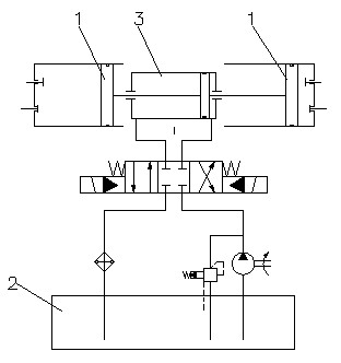
[0043] Please see Figure 4 , Figure 5 This embodiment describes a hydraulic oil piston natural gas substation compressor, which consists of high pressure oil pump 1, pressure control valve 2, pressure oil tank 3, liquid reversing valve 4, flow sensor 5, bridge valve group 6, gas Compression cylinder right tank 7, gas compression cylinder left tank 8, pressure sensor 9, pressure relay 10, high-pressure gas cylinder 11, automatic control system 12, oil replenishment system 13, inlet valve 14, outlet valve 15, check valve 16 And pressure gauge. An inlet valve 14 is installed beside the inlet of the inlet pipeline, and an outlet valve 15 is installed beside the outlet of the outlet pipeline. A pressure sensor 9 is provided behind the inlet valve 14, and the inlet pipeline behind the pressure sensor 9 is connected to the pressure oil tank 3 and the bridge valve group 6 through a three-way pipe. The bridge valve group 6 consists of four one-way valves. The valve is composed of two open ends of the one-way valve close to the inlet pipeline and the two check ends of the one-way valve close to the outlet pipeline are arranged oppositely. An outlet pipeline is arranged on the diagonal of the inlet pipeline of the bridge valve group 6, and a high-pressure gas cylinder 11 is installed on the outlet pipeline via a three-way pipe, and the outlet three-way pipe is connected to the bridge valve group 6 There is a pressure relay 10 between them; the other diagonal line of the bridge valve group 6 is respectively equipped with a gas compression cylinder right tank 7 and a gas compression cylinder left tank 8. The bottom ends of the two gas compression cylinders are in sequence Through the electro-hydraulic reversing valve 4, the flow sensor 5 and the high-pressure oil pump 1, it is connected to the bottom end of the pressure oil tank 3. The bottom end of the right tank 7 of the gas compression cylinder passes through a channel of the electro-hydraulic reversing valve 4 through a pipeline. The bottom end of the pressure oil tank 3 is connected to form a closed circulation loop; the electro-hydraulic directional valve 4 uses a three-position four-way valve. A pipe is also provided between the fuel injection port of the high-pressure oil pump 1 and the bottom of the pressure oil tank 3, and a pressure control valve 2 is installed on the branch pipe; a check valve is provided between the flow sensor 5 and the high-pressure oil pump 1, The non-return end of the check valve faces the flow sensor 5. The positions of the gas compression cylinder right tank 7 and the gas compression cylinder left tank 8 are higher than the pressure oil tank 3. Under static pressure, the lowest liquid level of the gas compression cylinder right tank 7 and the gas compression cylinder left tank 8 and the pressure oil tank 3 The highest liquid level is on the same level; an oil replenishment system 13 is arranged at the bottom end of the pressure oil tank 3 to replenish the pressure oil tank in time. The fuel quantity signal measured by the flow sensor 5 and the pressure signal measured by the pressure sensor 9 are transmitted to the automatic control system 12 at the same time, and sent to the electro-hydraulic directional valve 4 after being processed. The electro-hydraulic directional valve 4 receives the instruction Control the switching of the left and right tanks of the gas compression cylinder. The pressure relay 10 transmits the measured pressure signal to the automatic control system 12, and the automatic control system 12 instructs the high-pressure oil pump 1 to start and pump high-pressure oil.
[0044] In order to make the gas entering the circulation circuit clean, a gas filter is installed on the inlet pipe of the pressure sensor 9 and the pressure oil tank 3. In order to detect the air pressure entering the bridge valve group 6, between the gas filter and the bridge valve group 6 There is a pressure gauge on the inlet pipeline. In order to detect the outlet pressure, a pressure gauge is arranged between the high-pressure gas cylinder 11 and the outlet valve 15 to facilitate the detection of the outlet pressure at any time.
[0045] The compressor of the present invention works as follows: The gas source-a natural gas transportation tanker is connected to the compressor inlet with a high-pressure hose. At this time, the compressor is static and not turned on, and the inside of the machine is at a normal pressure. When the valve is opened, the natural gas passes through the gas filter, enters the three-way pipe at one end and enters the pressure tank 3 down, and the other end enters the bridge valve group 6, and opens all the one-way valves of the bridge valve group 6, all the way through the pressure relay 10 into high pressure After the gas cylinder 11 is stored and ready to be sent. The pressure relay 10 also conforms to the setting of 20 MPa pressure value due to the high pressure of natural gas, and does not start the compressor. The other two gases in the bridge valve group 6 also enter the right tank 7 of the gas compression cylinder and the left tank 8 of the gas compression cylinder at the same time, such as Figure 4 The state shown is the pressure equilibrium state.
[0046] When the pressure of the high-pressure gas storage cylinder 11 decreases due to gas delivery (Note: the pressure of the gas storage tanker includes a decrease in the gas storage pressure) is lower than the set value of the pressure relay 10, the compressor hydraulic pressure boosting system is activated and automatically The control system 12 instructs the high-pressure oil pump 1 to send the high-pressure oil through the flow sensor 5 and then through the electro-hydraulic directional valve 4, into any gas compression cylinder tank. As the volume of the hydraulic oil increases, the compressed gas pressure increases. When the high-pressure gas moves to the high-pressure gas cylinder 11, the high-pressure gas closes the one-way valve leading to the low pressure when passing through the bridge valve group 6, and the high-pressure gas can only enter the high-pressure gas cylinder 11, such as Figure 5 Shown.
[0047] Here, the volume flow of the high-pressure oil sent by the high-pressure oil pump 1 to the gas compression cylinders 7 and 8 is equivalent to the stroke of the piston in a piston compressor. The stroke of this "oil piston" is adjustable, and it changes according to pressure. Under the circumstances, gradually adjust the amount of high-pressure oil entering, that is, the length of the stroke of the "oil piston" to adapt to changes in pressure. When the pressure is high, the compression stroke is short; when the pressure is low, the compression stroke is longer. The flow sensor 5 adds the measured oil quantity signal to the pressure signal measured by the pressure sensor 9 at the inlet of the compressor and transmits it to the control system 12 at the same time. The pressure of natural gas in the high-pressure gas cylinder 11 always maintains the output value. The output pressure of the high-pressure oil pump 1 is adjusted by the pressure regulating valve 2.
[0048] The above are only the preferred embodiments of the present invention and are not intended to limit the present invention. Any modification, equivalent replacement and improvement made within the spirit and principle of the present invention shall be included in the protection of the present invention. Within range.