
Fatigue property test method for wallboard lap joint structure

A technology of fatigue performance and test method, which is used in the testing of machine/structural components, testing of mechanical components, measuring devices, etc. It can solve the problems of insufficient accuracy, prediction deviation, and difference in fatigue life, which cannot be used for fatigue life prediction. , to achieve the effect of eliminating bending deformation, ensuring effectiveness, and good test results

Inactive Publication Date: 2012-01-18
AIR FORCE UNIV PLA
View PDF4 Cites 3 Cited by
  • Summary
  • Abstract
  • Description
  • Claims
  • Application Information

AI Technical Summary

Problems solved by technology

[0003] However, the stress analysis of the connectors, especially the local detailed stress analysis, due to the uniqueness of the structural form of the connectors, the simultaneous contact and plastic deformation is a complex nonlinear process, which makes the calculation error very large, so that the structural analysis and Great inconvenience by design, life estimates are more spread out
For the influence of different stress states caused by the thickness of the specimen, in the process of life estimation, the local stress-strain method is used to deal with the modified Neuber method and linear interpolation method, resulting in prediction deviation
Using a three-dimensional contact model to calculate the stress severity factor of a certain part is more accurate, but it often requires a lot of calculation for large-scale connector analysis
However, the method of using two-dimensional nail elements to simulate fasteners can easily calculate the stress severity coefficient of the hole, but the influence of thickness and load is not taken into account, and the accuracy is not high enough.
The difference in fatigue life of materials with different thicknesses cannot be predicted by fatigue life, which is one of the major defects in existing life prediction methods

Method used


Image

  • Fatigue property test method for wallboard lap joint structure
  • Fatigue property test method for wallboard lap joint structure
  • Fatigue property test method for wallboard lap joint structure

Examples


Embodiment Construction

[0022] Now in conjunction with embodiment, accompanying drawing, the present invention will be further described:

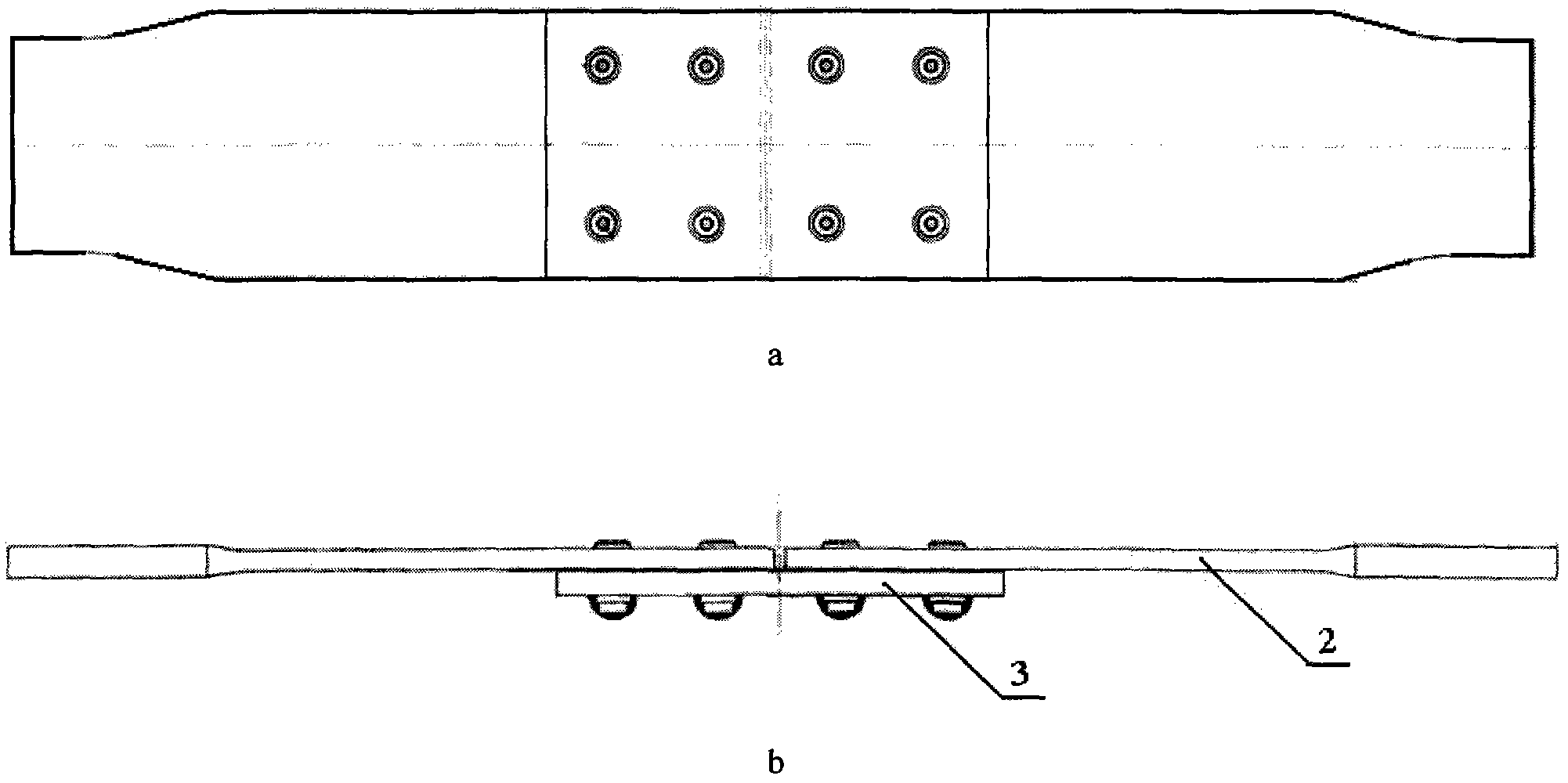
[0023] Test piece: typical wall panel lap joint structure, the material of the load-carrying plate and the butt plate is LY12-CZ aluminum alloy, and the bolt material is 30CrMnSiNi2A. The dimensions of the test piece are shown in Figure 5.

[0024] Step 1 Installation of test pieces:

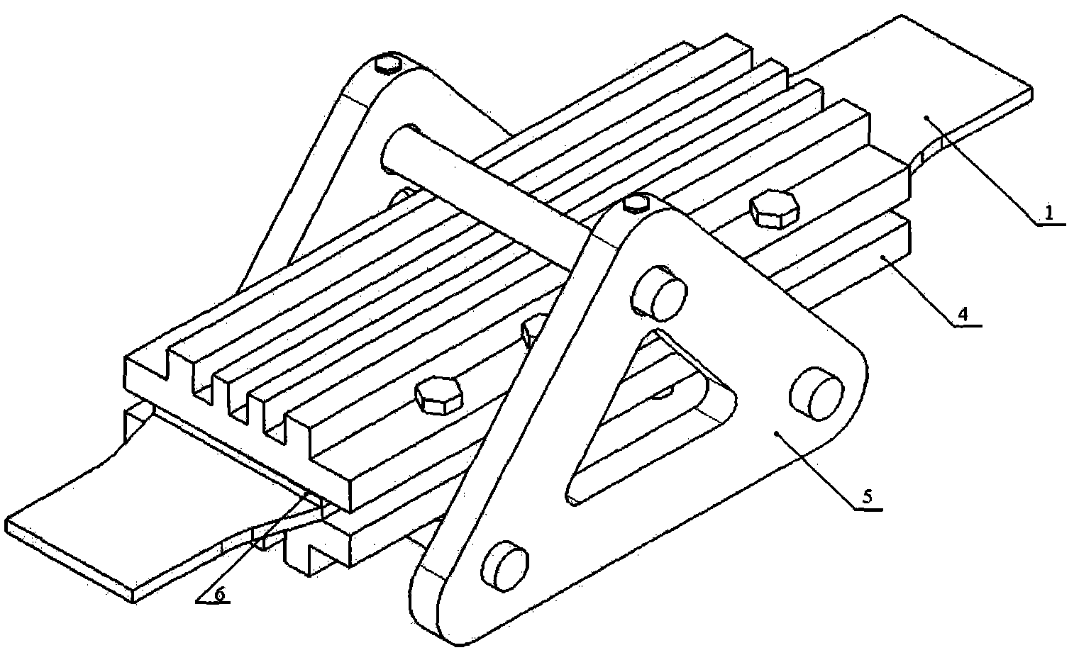
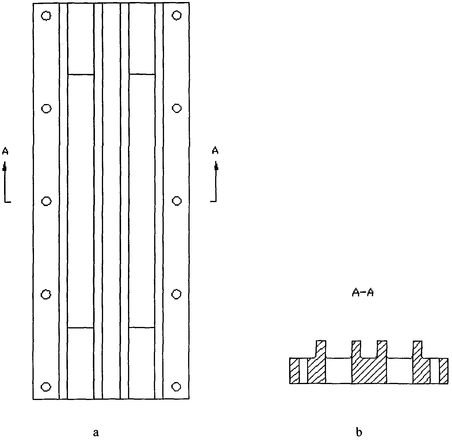
[0025] Step a) Clamp the splint 4 directly on both sides of the test piece and connect it with bolts; add a 12mm thick aluminum alloy spacer 6 between the butt plate 2 and the splint 4; The contact part is coated with grease added with molybdenum disulfide, and the polytetrafluoroethylene film is used as a lubricating strip;

[0026] Step b): install a triaxial bending limiting device 5 outside the splint 4, and tighten the bolts on the splint 4 and the triaxial bending limiting device 5 to 17Nm with a torque wrench;

[0027] Step c): Clamp the two ends of the test piece with th...


PUM


Abstract

The invention relates to a fatigue property test method for a wallboard lap joint structure. The fatigue property test method is characterized by comprising the following steps of: installing a test piece in a triaxial bending-limitation clamp; clamping two ends of the test piece by using an upper chuck and a lower chuck of a tester, wherein the centering line of the two chucks is overlapped with the central line of the two ends of the test piece; then prestretching a connection piece twice; continuing to load a sine waveform with a frequency of 5 Hz, wherein the peak value of the load is 0.3[P]n; and reducing the frequency by 1 Hz every 1,000-3,000 times so as to acquire the length a of a crack at each time and a corresponding load cycle number N. The fatigue property test method has the beneficial effects that a fatigue crack extension test for the wallboard lap joint structure with longitudinal load can be carried out; a good test effect is achieved during actual use; and furthermore, any obvious vibration or deformation can be avoided, bending deformation can be eliminated effectively, axial load transmission and deformation cannot be influenced and the effectiveness of test data is guaranteed.

Description

technical field [0001] The invention relates to a fatigue performance test method of a typical wall-board lap joint structure, and particularly provides a set of fixture devices for the fatigue test of the wall-board lap joint structure and a generalized fatigue notch coefficient model. Background technique [0002] There are a large number of structural connectors in aerospace structures. Many important load-bearing components are connected to other structures by fasteners such as bolts and rivets. The test and calculation of connectors are affected by many factors, such as the connection form (lap joint or butt joint, single shear or double shear, etc.), the geometric dimensions of the connection (row distance, end distance, ratio of side distance to aperture, etc.), fasteners The type and size of the load, the type of load (static load, dynamic load or fatigue load), direction, ambient temperature, humidity, medium) and other factors. The fatigue performance analysis of...

Claims


Application Information

Patent Timeline
Patent Type & Authority Applications(China)
IPC IPC(8): G01M13/00
Inventor 何宇廷崔荣洪伍黎明杜金强刘仁宇张海威丁华
Owner AIR FORCE UNIV PLA
Learn More