Design method of scanning unit based on partial scanning of improved test vector set
A technology of test vectors and scanning units, applied in the direction of measuring electricity, measuring devices, measuring electrical variables, etc., can solve problems such as hardware redundancy and large memory capacity, reduce storage space, reduce hardware redundancy, and facilitate test compression and the effect of vector generation
- Summary
- Abstract
- Description
- Claims
- Application Information
AI Technical Summary
Problems solved by technology
Method used
Image
Examples
specific Embodiment approach 1
[0064] Specific Embodiment 1: In the design method of the scanning unit based on partial scanning of the improved test vector set described in this embodiment,
[0065] Firstly, the important equivalent output pins that are important for fault detection are obtained by using the method of fault simulation on the equivalent output pins of the sequential circuit combination;
[0066] Then, the improved test vector set is obtained by simulating the faults of the equivalent input pins of the sequential circuit combination;
[0067] Finally, according to the improved test vector set and the equivalent output pins that are not important for fault detection, the flip-flops are divided into fixed-input flip-flops and important flip-flops, and the important flip-flops are connected in series to form a partial scan chain.
[0068] The given input flip-flops are don't care flip-flops, 0 don't care flip-flops and 1 don't care flip-flops.
[0069] The method of carrying out fault simulati...
specific Embodiment approach 2
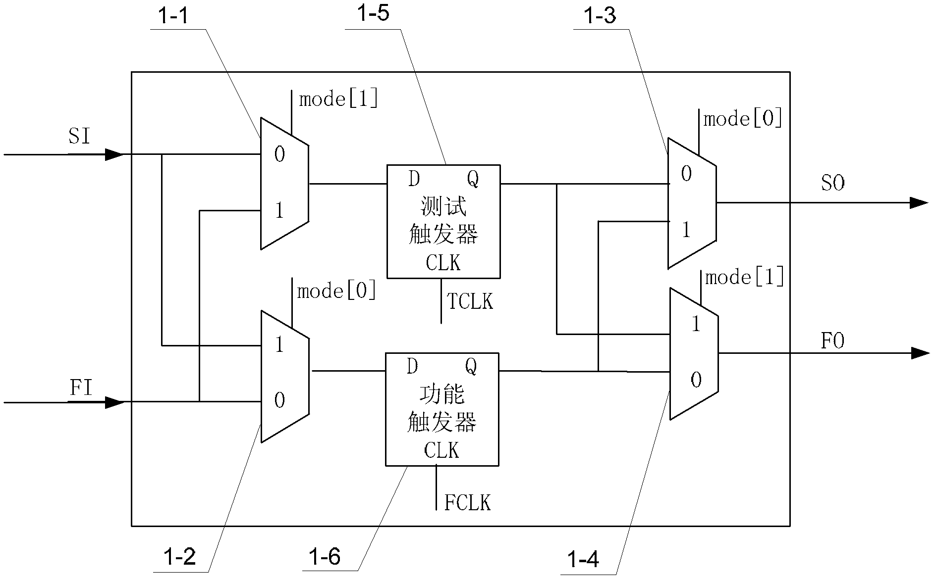
[0102] Specific Embodiment 2: This embodiment is a further description of the important triggers described in Specific Embodiment 1. image 3 with Figure 9 This embodiment will be described.
[0103] The important trigger 1 in this embodiment includes a first selector 1-1, a second selector 1-2, a third selector 1-3, a fourth selector 1-4, a test trigger 1-5 and a function triggers 1-6,
[0104] The input signal of the enable terminal of the first selector 1-1 is mode[1], the input signal of the enable terminal of the second selector 1-2 is mode[0], and the input signal of the enable terminal of the third selector 1-3 The signal is mode[0], and the input signal of the enable terminal of the fourth selector 1-4 is mode[1];
[0105] The 0 input terminal of the first selector 1-1 is used as the test unit scan data input terminal of the important flip-flop 1, and the test scan data SI is input, and the 1 input terminal of the first selector 1-1 is connected with the second sel...
specific Embodiment approach 3
[0147] Specific Embodiment 3. This embodiment is a further description of the irrelevant trigger described in Specific Embodiment 1. Refer to Figure 12 As shown, the irrelevant flip-flop described in this embodiment is composed of a selector and a D flip-flop, the 0 input end of the selector is connected to the data output end of the D flip-flop, and the data output end of the selector is connected to the D flip-flop The data input end of the D flip-flop is the data output end of the irrelevant flip-flop.
PUM
 Abstract
Description
Claims
Application Information
 - R&D
- Intellectual Property
- Life Sciences
- Materials
- Tech Scout
- Unparalleled Data Quality
- Higher Quality Content
- 60% Fewer Hallucinations
Browse by: Latest US Patents, China's latest patents, Technical Efficacy Thesaurus, Application Domain, Technology Topic, Popular Technical Reports.
© 2025 PatSnap. All rights reserved.Legal|Privacy policy|Modern Slavery Act Transparency Statement|Sitemap|About US| Contact US: help@patsnap.com


