Hopping frequency synthesizer for front end of millimeter wave holographic imaging system

A technology of frequency hopping frequency and holographic imaging, which is applied to the automatic control of power and electrical components, etc., can solve the problems that cannot satisfy the millimeter wave holographic imaging system and the long time of frequency conversion, and achieve low phase noise, fast frequency hopping, and low cost effect

Inactive Publication Date: 2012-01-18
SHANGHAI INST OF MICROSYSTEM & INFORMATION TECH CHINESE ACAD OF SCI
View PDF3 Cites 7 Cited by
  • Summary
  • Abstract
  • Description
  • Claims
  • Application Information

AI Technical Summary

Problems solved by technology

This single-loop method can achieve a very high output frequency and has good phase noise and spurious characteristics. The disadvantage is that the frequency conversion time is long (see Jin Guoqiong, L-band low phase noise, fast locking frequency synthesizer development, electronic Confrontation, 2009, 2(2): 32-37; Wu Yongjun, Shen Baosuo, Research on Frequency Conversion Speed ​​and Spectrum Purity of Frequency Hopping Frequency Synthesizer, Journal of Tianjin University of Technology, 2002, 21(1): 20-23)
Therefore, directly applying the existing frequency hopping frequency synthesizer cannot meet the requirements of the millimeter-wave holographic imaging system, which requires an improved frequency synthesizer, so that due to the purpose of the present invention

Method used


Image

  • Hopping frequency synthesizer for front end of millimeter wave holographic imaging system
  • Hopping frequency synthesizer for front end of millimeter wave holographic imaging system
  • Hopping frequency synthesizer for front end of millimeter wave holographic imaging system

Examples


Embodiment Construction

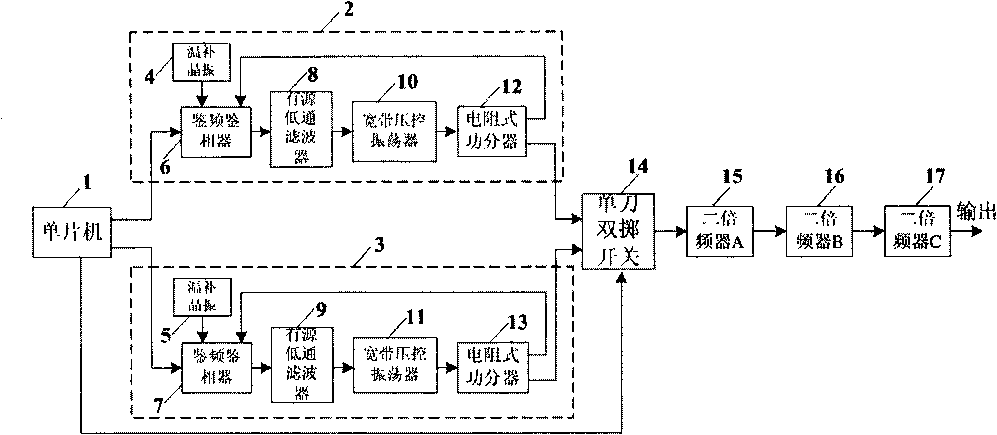
[0016] A preferred embodiment of the present invention is described in detail as follows in conjunction with the accompanying drawings: The block diagram of the double-loop frequency hopping frequency synthesizer is as follows figure 1 shown. This embodiment includes: a single-chip microcomputer 1, a single-channel phase-locked loop circuit 2, another single-channel phase-locked loop circuit 3, a single-pole double-throw switch 14, a frequency doubler A15, a frequency doubler B16 and a frequency doubler C17. Single-chip microcomputer 1 controls the frequency hopping of phase-locked loop circuit 2 and phase-locked loop circuit 3 and the opening or closing of SPDT switch 14, and the signal output by SPDT switch 14 passes through doubler A15, doubler B16 and two Frequency multiplier C17 outputs after three-stage frequency multiplication.

[0017] The single-channel phase-locked loop circuit 2 is composed of a temperature-compensated crystal oscillator 4 , a frequency and phase d...


PUM


Abstract

The invention relates to a hopping frequency synthesizer for a front end of a millimeter wave holographic imaging system, which consists of a multipath phase-locked loop, a single-pole multi-throw switch, a frequency multiplier and a singlechip. The singlechip controls the frequency hopping of the multipath phase-locked loop and the on or off of the single-pole multi-throw switch. The multipath phase-locked loop comprises N single-path phase-locked loops, the N paths are more, the frequency conversion time of the whole frequency hopping source is shorter, and the frequency hopping time of the N paths of phase-locked loops is one Nth of that of the single path loop. The single-path phase-locked loop comprises a crystal oscillator, a frequency and phase detector, a filter, a voltage-controlled oscillator and a power divider, wherein the input of the frequency and phase detector is connected with the crystal oscillator and the feedback signal which is provided by the voltage-controlled oscillator, the output of the frequency and phase detector is connected with the filter, the power divider divides the output of the voltage-controlled oscillator into two paths, one path is output to the single-pole multi-throw switch, and the other path is fed back to the frequency and phase detector. The hopping frequency synthesizer outputs the wideband millimeter wave signals of 24 GHz-36GHz.

Description

technical field [0001] The present invention relates to a frequency hopping frequency synthesizer used in the front end of a millimeter wave holographic imaging system, more precisely to a phase-locked loop frequency synthesizer with a fast frequency hopping function, which can be used as the base of a millimeter wave holographic imaging system vibration signal source. Background technique [0002] The millimeter-wave holographic imaging system is based on the principle of millimeter-wave reflection, and uses reflected millimeter-wave to scan and detect the human body. It can display the detection results, which can meet the needs of human body security inspection in airports, stations, important gatherings and other places. Compared with the passive millimeter-wave imaging system, the millimeter-wave holographic imaging system is active, which requires a millimeter-wave local oscillator generator. When the millimeter-wave local oscillator can realize fast frequency hoppin...

Claims


Application Information

Patent Timeline
Patent Type & Authority Applications(China)
IPC IPC(8): H03L7/18
Inventor 孙晓玮陈敏华时翔李江夏李凌云
Owner SHANGHAI INST OF MICROSYSTEM & INFORMATION TECH CHINESE ACAD OF SCI
Why Eureka
Try Eureka