Floatation device

A flotation device and flotation column technology, which is applied in flotation, solid separation, etc., can solve the problems of less chance of mineralized foam floating up, increased processing difficulty, and inability to uniformly fill the bubbles, so as to improve mineral mineralization chance, reduce the difficulty of maintenance, and evenly distribute the foam

Active Publication Date: 2012-01-25
CHANGGAO ELECTRIC GROUP CO LTD
View PDF9 Cites 14 Cited by
  • Summary
  • Abstract
  • Description
  • Claims
  • Application Information

AI Technical Summary

Problems solved by technology

The air-filled spray gun arranged at the bottom of the flotation column can mineralize the tailings at the bottom of the flotation column, but when these mineralized foams float upward, they encounter the resistance of the downstream ore pulp, making the probability of these mineralized foams to float upwards very small. These mineralized foams are finally discharged with the tailings, and the recovery rate of the flotation column is affected
[0004] 2. The bubbles coming out of the inflatable spray gun are in the shape of an inverted cone, and any section in the column cannot be uniformly filled with bubbles, resulting in the inability to fully contact with the downstream pulp; and because the bubbles have a large kinetic energy, they are easy to float to the top of the flotation column , reducing the contact probability of air bubbles and pulp, greatly affecting the recovery rate of the flotation column
However, with the increase of the length of the spray gun, the positioning of the long spray gun is not accurate, the foaming effect is not ideal, the processing difficulty is increased, and the spare parts are not uniform, so that the flotation effect is not ideal, and it also increases the difficulty of maintenance and replacement.

Method used


Image

  • Floatation device
  • Floatation device
  • Floatation device

Examples


Embodiment Construction

[0023] The present invention will be further described in detail below in conjunction with the accompanying drawings and specific embodiments.

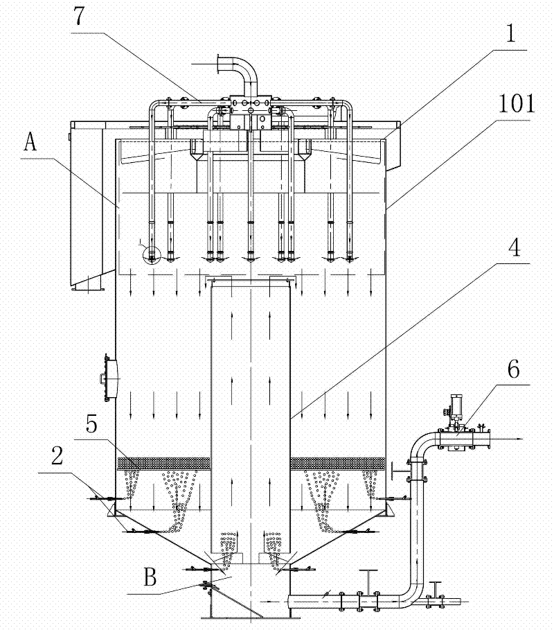
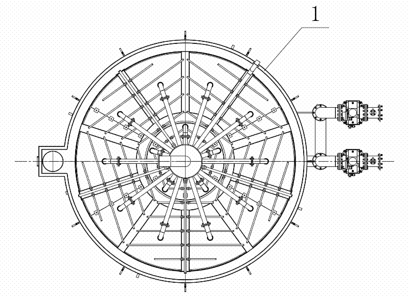
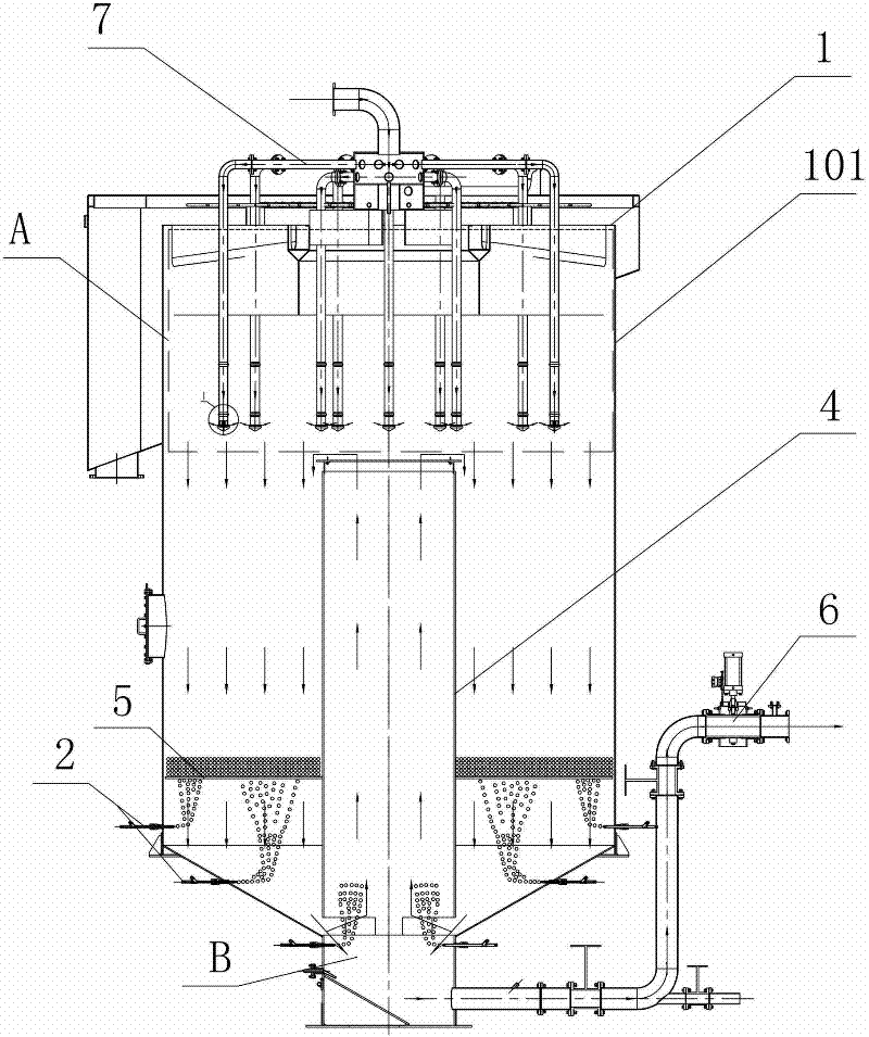
[0024] Such as figure 1 and figure 2 As shown, the flotation device of the present invention comprises a flotation column 1, a feed assembly 7 and a tailings discharge assembly 6 connected to the bottom of the flotation column 1, and the feed assembly 7 is positioned at the top of the flotation column 1, vertically Bottom layout, the slurry is fed from top to bottom; area A in the figure is the concentrate area, and area B in the figure is the tailings area. In the present invention, a scavenging channel 4 is provided in the column body 101 of the flotation column 1 . The sweeping channel 4 is tubular and located in the middle of the cylinder 101 , arranged along the vertical direction, with the lower end being the inlet end and the upper end being the outlet end. The inlet end is slightly higher than a part of the air-filled spra...


PUM


Abstract

The invention discloses a flotation device, which comprises a flotation column, a feeding component and more than one inflation ejection gun which is installed in the flotation column. A scavenging channel is arranged in a column body of the flotation column; the scavenging channel is pipe-shaped, is located at the middle part of the column body and is distributed along a vertical direction; the lower end of the scavenging channel is an inlet end and the upper end of the scavenging channel is an outlet end. The flotation device has the advantages of simple and compact structure, low cost, stable and reliable work, low operation cost, convenience in maintenance, simplicity in operation, good flotation effect, wide application range and the like.

Description

technical field [0001] The invention mainly relates to the field of mineral flotation equipment, in particular to a flotation device. Background technique [0002] As the key equipment of mineral flotation, flotation column has been widely used. However, the structure of the existing flotation column has the following deficiencies: [0003] 1. The air bubbles and pulp of the existing flotation column are "counter-current type", that is, the pulp flows downward and the foam floats upward. The air-filled spray gun arranged at the bottom of the flotation column can mineralize the tailings at the bottom of the flotation column, but when these mineralized foams float upward, they encounter the resistance of the downstream ore pulp, making the probability of these mineralized foams to float upwards very small. These mineralized foams are finally discharged with the tailings, and the recovery rate of the flotation column is affected. [0004] 2. The bubbles coming out of the inf...

Claims


Application Information

Patent Timeline
Patent Type & Authority Applications(China)
IPC IPC(8): B03D1/14
Inventor 马驰宇雷海兵
Owner CHANGGAO ELECTRIC GROUP CO LTD
Why Eureka
Try Eureka