Floor drain with functions of grinding and generating electricity

A floor drain and function technology, applied in the field of sanitary ware, can solve the problems of production, living inconvenience, blockage of drainage pipes, environmental pollution, etc., and achieve the effect of improving reliability and passing ability.

Inactive Publication Date: 2012-01-25
QINGDAO TECHNOLOGICAL UNIVERSITY
View PDF5 Cites 7 Cited by
  • Summary
  • Abstract
  • Description
  • Claims
  • Application Information

AI Technical Summary

Problems solved by technology

Especially for the drainage ends of large canteens, hotels, restaurants, etc., there are often solids, fibers, hairs, easy sediments, etc., which often cause blockage of drainage pipes, affect normal use and cause environmental pollution, which brings harm to people's production and life. serious inconvenience

Method used


Image

  • Floor drain with functions of grinding and generating electricity
  • Floor drain with functions of grinding and generating electricity
  • Floor drain with functions of grinding and generating electricity

Examples


Embodiment Construction

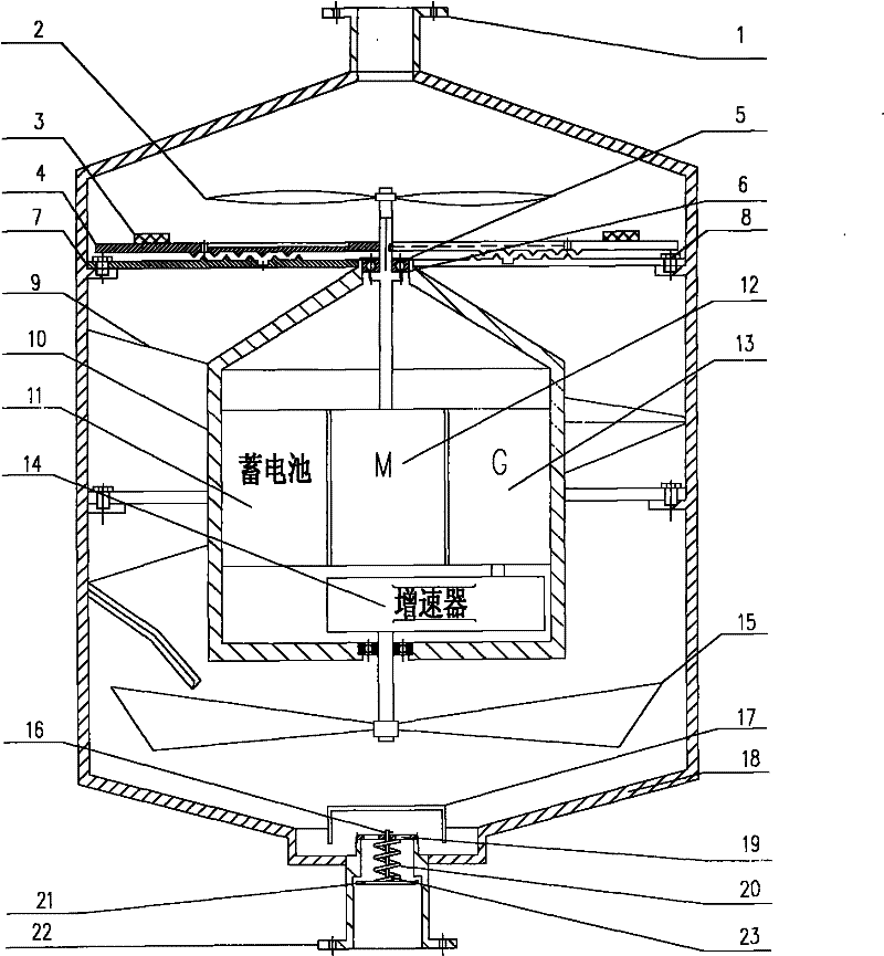
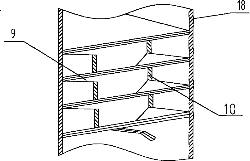
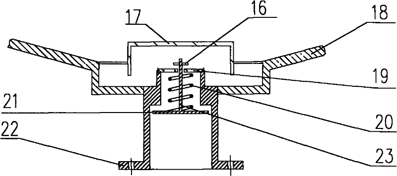
[0023] The general concept of the present invention is to use crushing blades, rotating grinding discs and fixed grinding discs to realize the crushing of wastes, which improves the reliability and throughput of the equipment; the use of annular diversion grooves makes the discharge of wastes faster, and the impact drives the power generation blades at a high speed. Rotate to generate electricity. Introduce a kind of embodiment below in conjunction with accompanying drawing: figure 1 Shown is a structural schematic diagram of an embodiment, consisting of an upper end cover 1, a crushing blade 2, a pressure sensor 3, a rotating grinding disc 4, a sealing ring 5, a rolling bearing 6, a fixed grinding disc 7, connecting bolts 8, an annular flow guide groove 9, an inner Box 10, battery 11, motor 12, generator 13, speed increaser 14, power generation blade 15, retaining spring 16, deodorant end cover 17, outer box 18, drainage inner cover 19, spring 20, sealing cover 21, The lower...


PUM


Abstract

The invention relates to the technical field of a sanitary ware, i.e. a floor drain with functions of grinding and generating electricity. The floor drain is characterized in that a rotary millstone (4) is arranged at the lower ends of grinding blades (2) and is fixedly connected with an electric motor (12); a fixed millstone (7) is arranged at the lower end of the rotary millstone (4) and is connected with an outer box body (18) through a connecting bolt (8); and a ring-shaped diversion trench (9) is positioned between the fixed millstone (7) and electricity generating blades (15). The floordrain has the beneficial effects that due to the adoption of the grinding blades, the rotary millstone and the fixed millstone, the grinding of effluent is realized and the reliability and the carrying capacity of equipment are improved; due to the adoption of the ring-shaped diversion trench, the effluent discharge speed is accelerated and the electricity generating blades are impacted and driven to rotate at a high speed to realize electricity generation; the difficult problems that the existing drainage floor drain is easy to block and has poor reliability, so that the normal use of the existing drainage floor drain is influenced and the environment pollution is caused are well solved; the electricity generation in the draining process is realized; and the floor drain is a high-efficiency, energy-saving and environmental-friendly sanitary ware product.

Description

technical field [0001] The invention relates to the technical field of sanitary ware, namely a floor drain with crushing and power generation functions. Background technique [0002] The floor drain is an important interface connecting the water end and the drainage pipe system, and its performance directly affects the drainage efficiency and indoor air quality. Especially for the drainage ends of large canteens, hotels, restaurants, etc., there are often solids, fibers, hairs, easy sediments, etc., which often cause blockage of drainage pipes, affect normal use and cause environmental pollution, which brings harm to people's production and life. Serious inconvenience. Contents of the invention [0003] The purpose of the present invention is to provide a floor drain with no clogging, fast drainage speed, good deodorization effect and power generation function, that is, a floor drain with crushing and power generation functions. [0004] The above object is achieved by t...

Claims


Application Information

Patent Timeline
Patent Type & Authority Applications(China)
IPC IPC(8): E03C1/28
Inventor 李长河
Owner QINGDAO TECHNOLOGICAL UNIVERSITY
Why Eureka
Try Eureka