Gasifying combustion device for liquid fuel
A technology for liquid fuels and combustion devices, applied in the directions of burners, combustion types, combustion methods, etc., can solve problems such as hidden safety hazards, complex structures, restrictions, etc., to achieve easy assembly and maintenance, improve combustion efficiency, and simplify the gasification process. Effect
- Summary
- Abstract
- Description
- Claims
- Application Information
AI Technical Summary
Problems solved by technology
Method used
Image
Examples
Embodiment 1
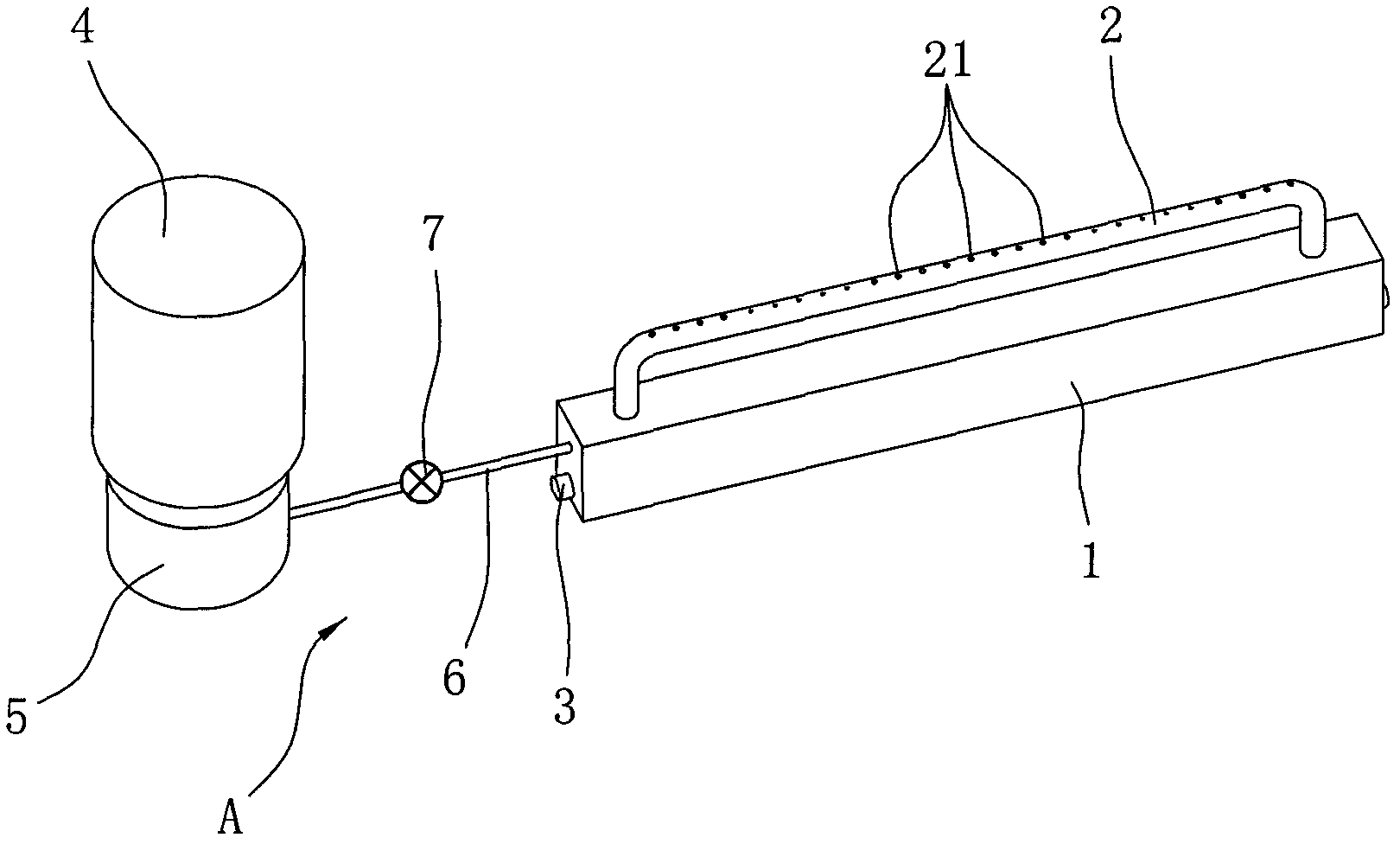
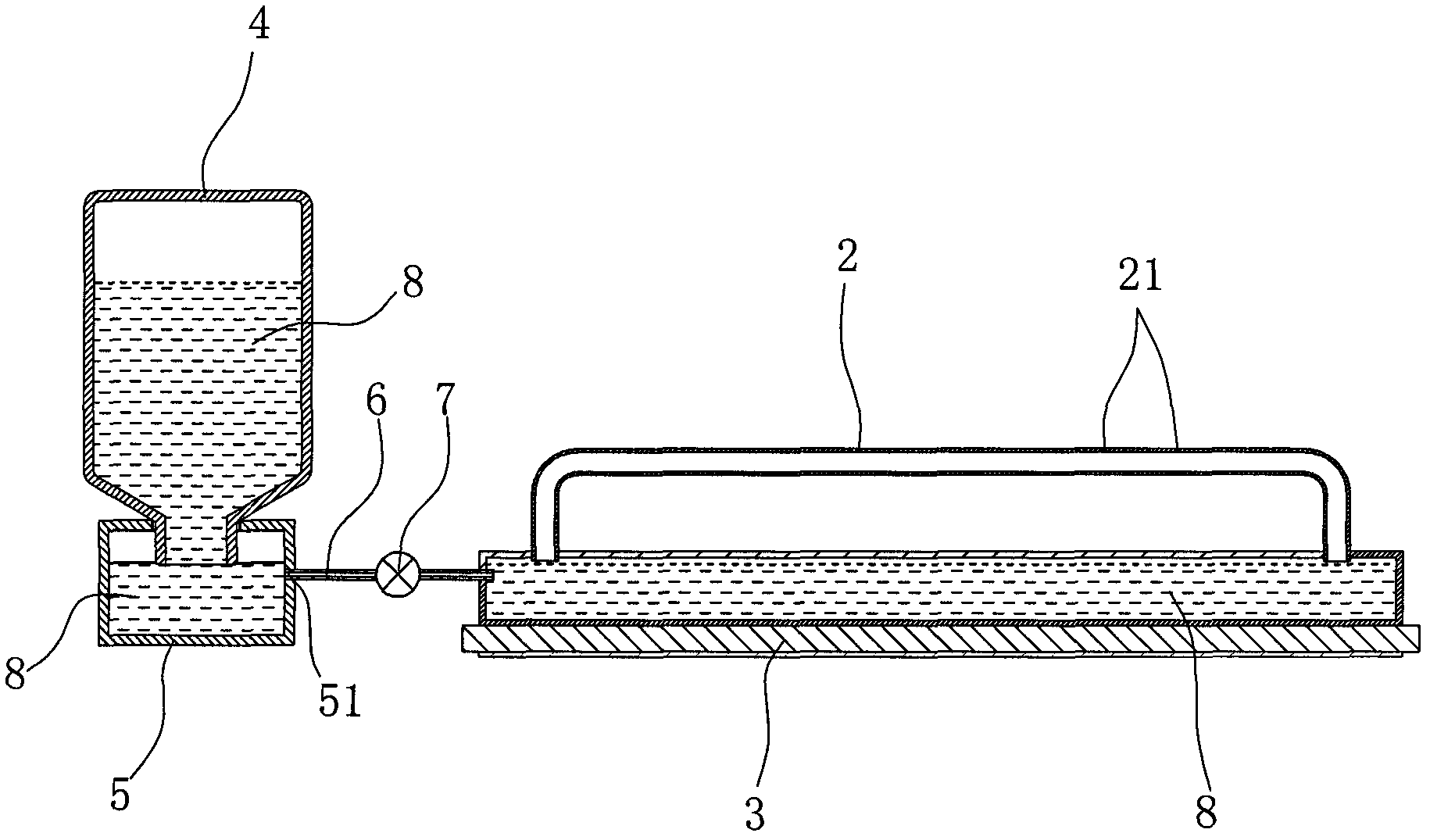
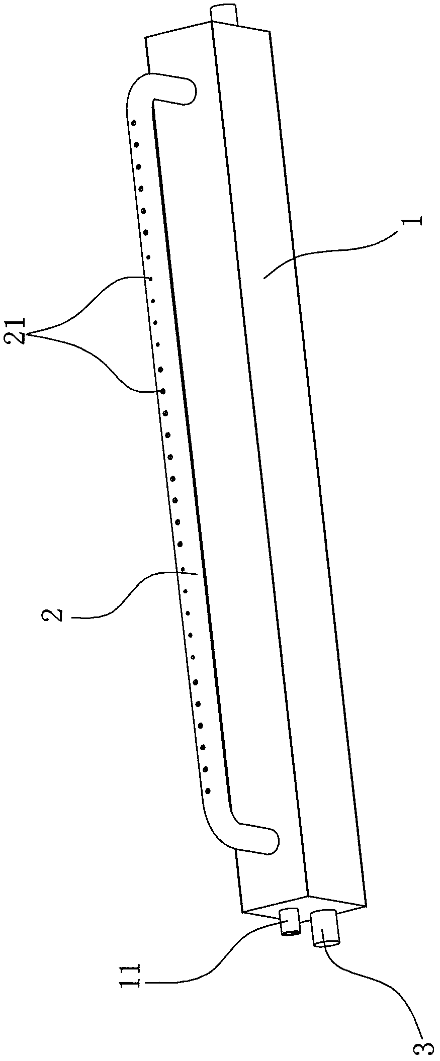
[0025] Embodiment one, such as Figure 1 ~ Figure 4 Show:
[0026] This embodiment is a liquid fuel gasification combustion device, which can be used in various living and industrial fields, such as fireplace products, stove products or industrial burners and so on.
[0027] The liquid fuel gasification combustion device includes a liquid supply device A, a gasification chamber 1, a burner 2 and an electric heating device 3, wherein the liquid supply device A includes a storage tank 4, a liquid receiving cup 5 and a feed pipe 6. The storage tank 4 is turned upside down on the liquid cup 5, and the height of the mouth of the storage tank 4 and the liquid fuel 8 in the vaporization chamber 1 are kept on the same level. Due to the atmospheric pressure, the liquid cup 5 The liquid level inside will also be on the same level as the liquid level in the vaporization chamber 1 all the time. The side of the liquid receiving cup 5 is provided with a liquid outlet 51, and the side of th...
Embodiment 2
[0032] Embodiment two, such as Figure 5 , Image 6 Shown:
[0033] The combustion device of this embodiment also includes a liquid supply device, a gasification chamber 1', a burner 2" and an electric heating device 3', wherein the liquid supply device includes a liquid fuel tank 4' and a feed pipe 5', and the gas The side of the chemical chamber 1' is provided with a liquid fuel filling port 11', and the liquid fuel tank 4' can be provided with a liquid outlet 41' on the top or side, and the two ends of the feed pipe 5' are respectively connected to the liquid outlet 41' and the liquid The fuel filling port 11' is also provided with an electromagnetic pump 6' that can realize flow regulation on the feed pipe 5', and the top of the liquid fuel tank 4' is provided with a liquid filling port 42', and the top of the liquid fuel tank 4' is also A liquid level indicator 43' is installed.
[0034] The structure and installation method of the burner 2' used in this implementation...
Embodiment 3
[0043] Embodiment three, such as Figure 7 , Figure 8 Shown:
[0044] The structure of the combustion device of this embodiment is basically the same as that of Embodiment 2, and the combustion device also includes a liquid fuel tank 4 ", a liquid level indicator 43 " arranged at the top of the liquid fuel tank 4 ", a feed pipe 5 ", an electromagnetic pump 6", gasification chamber 1", temperature sensor 12", liquid level sensor 13", burner 2", igniter 7", flame detection device 8", electric heating device 3", electromagnetic pump 6", temperature sensor 12 ", the liquid level sensor 13", the igniter 7", the flame detection device 8" and the electric heating device 3" are electrically connected through the electric control device 9";
[0045] The difference between the present embodiment and the second embodiment is the structure of the burner 2 ". The burner 2" of the present embodiment is flat and barrel-shaped, and the flame ejection hole 21 "is opened on the top of the bu...
PUM
 Abstract
Description
Claims
Application Information
 - R&D
- Intellectual Property
- Life Sciences
- Materials
- Tech Scout
- Unparalleled Data Quality
- Higher Quality Content
- 60% Fewer Hallucinations
Browse by: Latest US Patents, China's latest patents, Technical Efficacy Thesaurus, Application Domain, Technology Topic, Popular Technical Reports.
© 2025 PatSnap. All rights reserved.Legal|Privacy policy|Modern Slavery Act Transparency Statement|Sitemap|About US| Contact US: help@patsnap.com


