Device for moulding and forming drilled hole wall

A technology for shaping and forming the hole wall, which is applied in earthwork drilling, wellbore/well components, sealing/isolation, etc. It can solve the problems of increased drilling cost, easy falling off and accidents in the hole, etc., and achieves follow-up drilling The effect of small operation impact, easy promotion and application, and reduced operation time

Inactive Publication Date: 2012-02-01
安徽省地质矿产勘查局313地质队
View PDF5 Cites 2 Cited by
  • Summary
  • Abstract
  • Description
  • Claims
  • Application Information

AI Technical Summary

Problems solved by technology

In most cases, mud protection walls are used, but in some complex formations, it is difficult to meet the requirements simply by using mud protection walls; running casing can achieve the purpose of sealing off complex hole sections, but each time a casing is run, the diameter of the borehole It will be reduced by one level, which is not conducive to drilling construction, and the drilling cost will be greatly increased; the expansion tube technology used in oil drilling requires too much force to expand the expansion tube, the geological drilling equipment is not capable enough, and there are also some broken parts. The disadvantage that the formation cannot be lowered into place; when using cement wall protection, in some serious leakage and water gushing formations, the cement is easily diluted or washed away or does not congeal, and the cement hole wall formed between the cement and the hole wall is a rigid connection. After that, it is easy to fall off and block, and accidents in the hole occur.
Therefore, the above-mentioned technologies all have certain deficiencies, and it is difficult to meet the technical requirements of hole wall support in complex formations.

Method used


Image

  • Device for moulding and forming drilled hole wall
  • Device for moulding and forming drilled hole wall
  • Device for moulding and forming drilled hole wall

Examples


Embodiment

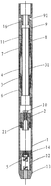
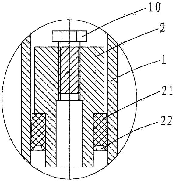
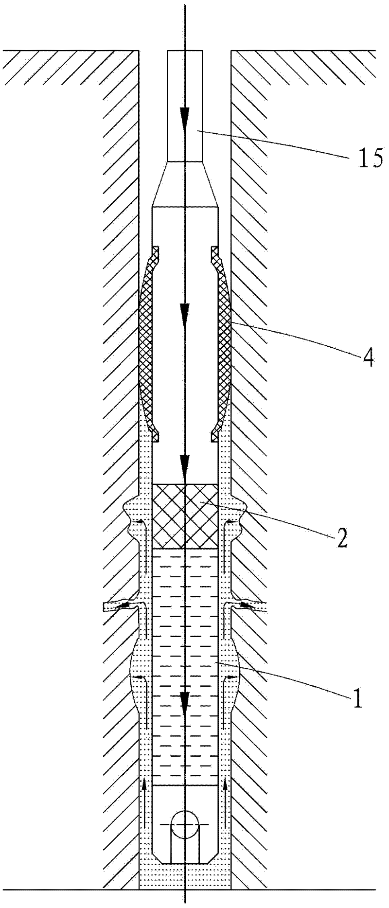
[0020] Example: see figure 1 , 2 , the drilling hole wall shaping device of the present embodiment includes:

[0021] The grout chamber 1 at the lower end, the lower end of the grout chamber 1 is threadedly connected with a hollow lower joint 12, and the lower end of the lower joint is threadedly connected with a hollow pilot joint 13, and the upper part of the inner cavity of the lower joint is provided with a round hole communicating with the inner chamber of the serous liquid chamber. A frustum-shaped passage, and a frustum-shaped lower piston 14 capable of blocking the frusto-conical passage is provided in the inner cavity of the lower joint. A spring 5 is also arranged in the inner cavity of the lower joint. The upper and lower ends of the spring 5 are respectively lowered by the lower piston 14 and the guide joint 13. For the spring seat. A piston seat 2 is arranged on the upper part of the inner cavity of the slurry chamber 1, a piston body 21 is sleeved on the lower ...


PUM


Abstract

The invention discloses a device for moulding and forming a drilled hole wall. The device for moulding and forming the drilled hole wall comprises a slurry bin, an expansion mechanism and a connecting mechanism, wherein, the slurry bin is positioned at the lower end of the device; the lower part of the slurry bin is provided with a one-way valve; a piston seat is arranged on the upper part of an inner cavity and is sealed with the inner wall of the slurry bin; the expansion mechanism is positioned on the middle part of the device and comprises a hollow core bar and an expansion pipe which is sleeved on the outer side of the hollow core bar; the lower part of the expansion pipe is tightly pressed through a lower pressure pipe; the upper end and the lower end of the lower pressure pipe are in threaded connection with the core bar and the slurry bin; the upper part of the expansion pipe is tightly pressed by an upper pressure pipe, and the upper pressure pipe is sleeved on the core bar; the connecting mechanism is positioned on the upper part of the device and comprises a hollow upper joint which is in threaded connection with the upper end of the core bar; the upper joint is provided with an inner thread which is connected with a drill rod; and radial small holes which are communicated with the inner cavity of the expansion pipe are formed on the core bar. The device for moulding and forming the drilled hole wall has the characteristics of low cost, good supporting effect, high supporting speed, and high safety and reliability; the device is connected with hole walls well, and the formed hole walls are high in elastoplasticity; and the device slightly abrades the drill rod and facilitates subsequent drilling operation.

Description

Technical field: [0001] The invention relates to a drilling hole wall shaping former. Background technique: [0002] In geological exploration, oil drilling, engineering survey and other drilling engineering drilling operations, the hole wall support technology of drilling complex strata is a big problem. In most cases, mud retaining walls are used, but in some complex formations, it is difficult to meet the requirements simply by using mud retaining walls; running casing can achieve the purpose of sealing off complex hole sections, but each time a casing is run, the diameter of the borehole It will be reduced by one level, which is not conducive to drilling construction, and the drilling cost will be greatly increased; the expansion tube technology used in oil drilling requires too much force to expand the expansion tube, the geological drilling equipment is not capable enough, and there are also some broken parts. The disadvantage that the formation cannot be lowered into...

Claims


Application Information

Patent Timeline
Patent Type & Authority Applications(China)
IPC IPC(8): E21B33/138
Inventor 朱恒银吴翔王强
Owner 安徽省地质矿产勘查局313地质队
Why Eureka
Try Eureka