Multi-rotor-wing automatic positioning detector used for transmission line

An automatic positioning and transmission line technology, applied in the direction of overhead lines/cable equipment, etc., can solve the problems of unsafe manual operation, complicated obstacle crossing process, low efficiency of manual line inspection, etc. The effect of ensuring safe and reliable operation and saving line inspection time

Inactive Publication Date: 2012-02-01
CHANGCHUN INST OF OPTICS FINE MECHANICS & PHYSICS CHINESE ACAD OF SCI
View PDF4 Cites 51 Cited by
  • Summary
  • Abstract
  • Description
  • Claims
  • Application Information

AI Technical Summary

Problems solved by technology

Human line inspection is inefficient, labor-intensive, and limited by the natural environment; vehicle inspection is limited by ground traffic, and vehicle inspection cannot be realized in many places; helicopter inspection is expensive, and it is difficult to achieve the required inspection accuracy ...

Method used


Image

  • Multi-rotor-wing automatic positioning detector used for transmission line
  • Multi-rotor-wing automatic positioning detector used for transmission line
  • Multi-rotor-wing automatic positioning detector used for transmission line

Examples


Embodiment 1

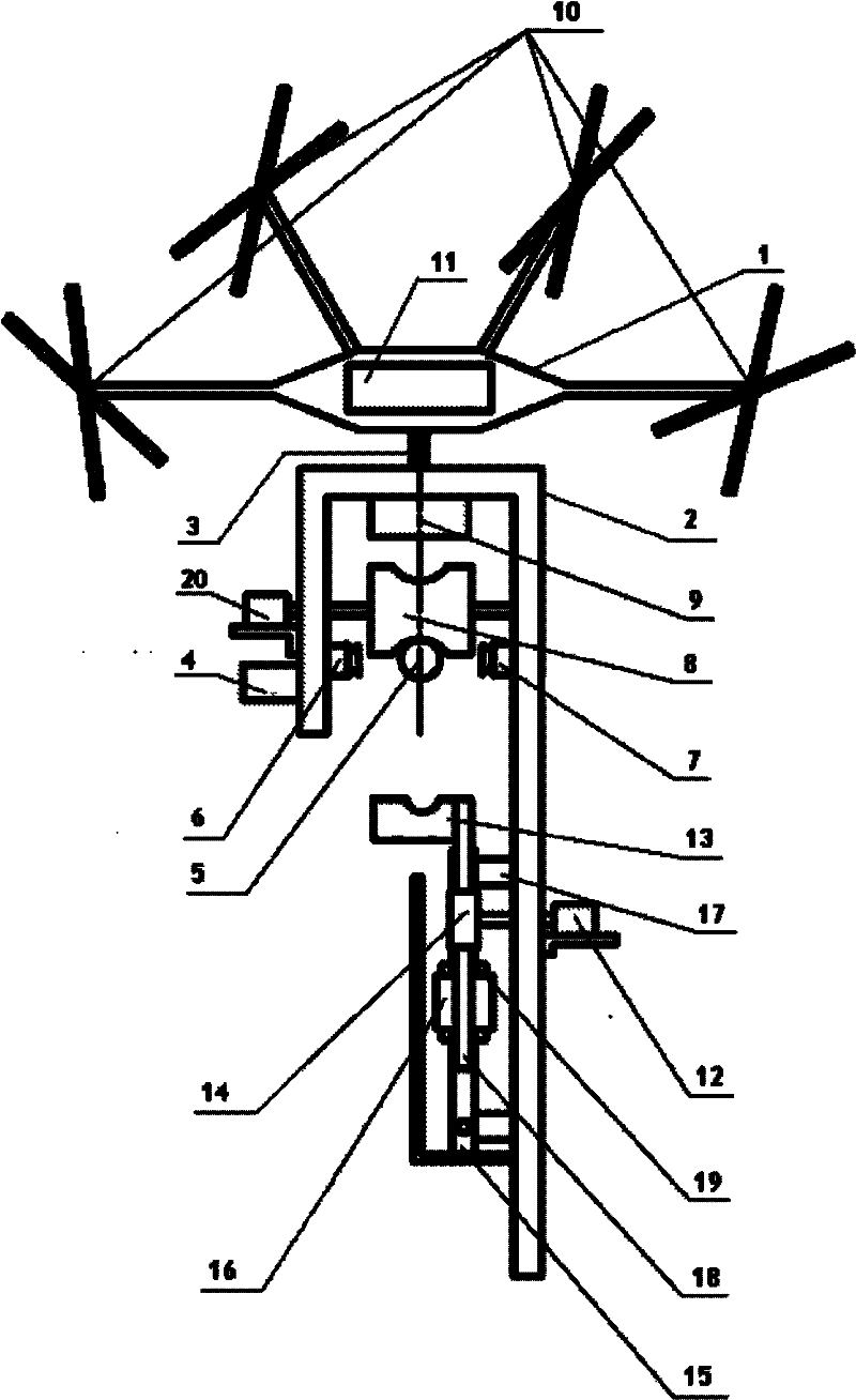
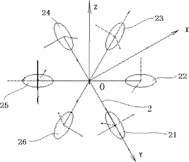
[0065] like Image 6 As shown, the body of the full-drive six-rotor micro air vehicle is provided with six connecting rods, which are evenly distributed around the body, and the outer ends of the six connecting rods are respectively connected to No. 1, No. 2, ..., No. , 26. Each rotor can be driven by a motor or an oil engine. The x and y axes of the aircraft body coordinate system are located in the plane where the six connecting rods are located and are perpendicular to each other. The z axis passes through the center of mass of the aircraft and is perpendicular to the plane where the six connecting rods are located. flat. The rotation planes of the six rotors form six inclinations with the xoy plane of the body coordinate system, and the rotation planes of each rotor are equal to the rotation planes of the third rotor separated by two rotors; the rotation planes of each rotor are the same as the adjacent rotors The inclination angle between the plane of rotation and the xo...

Embodiment 2

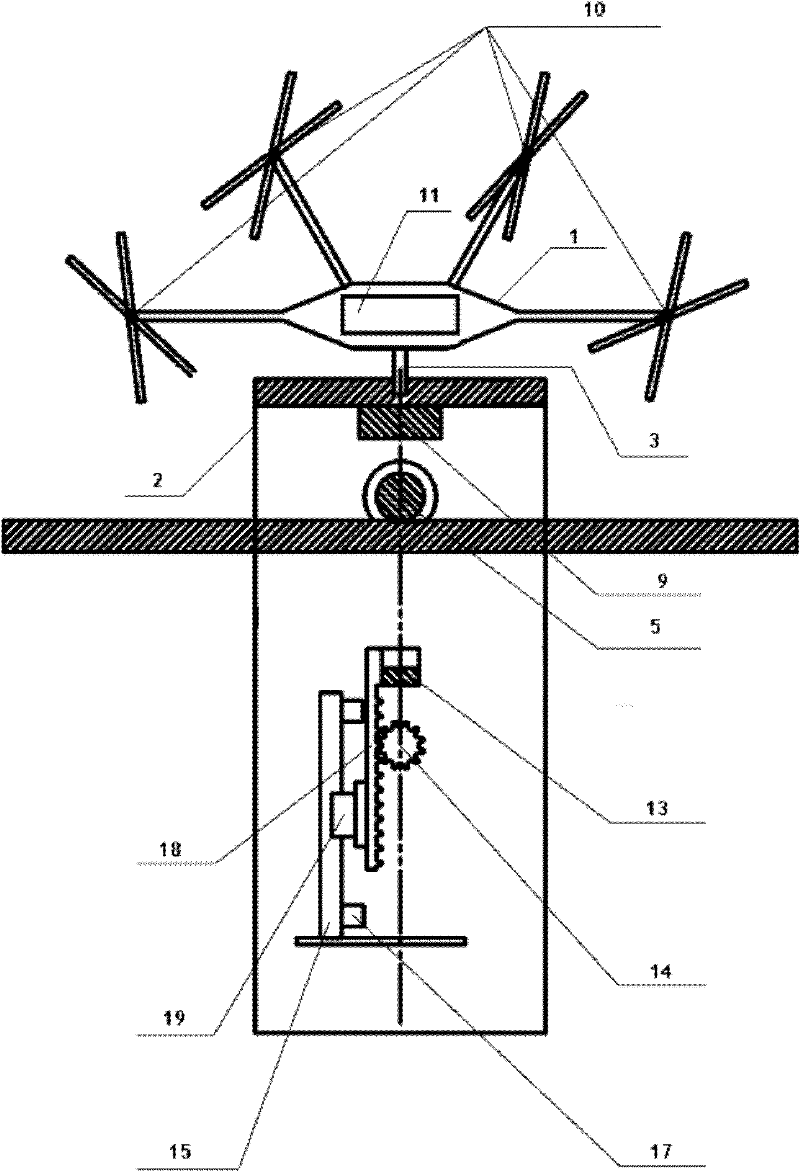
[0093] like Figure 7 As shown, the body of the underactuated six-rotor MAV is provided with three connecting rods, which are evenly distributed around the body. The outer end of each connecting rod is connected to the upper and lower rotors, and the first and second rotors 31 and 32 are connected to the same connecting rod No. 3 and No. 4 rotors 33 and 34 are connected to the outer ends of the same connecting rod, and No. 5 and No. 6 rotors 35 and 36 are connected to the outer ends of the same connecting rod. Each rotor can be driven by a motor or an oil engine.

[0094] The relationship between the virtual control quantity of the degree of freedom of the underactuated hexacopter MAV and the rotor speed is as follows:

[0095] U 21 U 22 U ...


PUM


Abstract

The invention relates to a multi-rotor-wing automatic positioning detector used for a transmission line. A patrol nacelle of the detector is fixedly connected with a multi-rotor-wing micro air vehicle by a connection structure; a master control board is fixed on the airframe of the multi-rotor-wing micro air vehicle; a power supply module is fixed on the patrol nacelle; a crawling mechanism is formed by a power device fixed on a side arm of the patrol nacelle and idler wheels connected with the power device; the master control board controls the power supply module to supply power for a driving mechanism of the multi-rotor-wing micro air vehicle or the power device of the crawling mechanism; an infrared video camera and a visible light camera are arranged on the inner wall of the patrol nacelle; the visible light camera is used for shooting the transmission line and the ambient environments and transmitting the information of the shot images to a ground station system by the master control board in real time; and the infrared video camera is used for detecting faults of the transmission line and transmitting the fault information to the ground station system by the master control board in real time. The multi-rotor-wing automatic positioning detector can be used in fields, has the advantages of high working efficiency and good safety, and has a real-time visual patrol function.

Description

technical field [0001] The invention relates to inspection equipment for ultra-high voltage transmission lines, in particular to a multi-rotor automatic positioning detector suitable for inspection of transmission lines. Background technique [0002] Power transmission must rely on high-voltage transmission lines. Its safe and stable operation directly affects the reliability of the power system. Due to the wide distribution of transmission lines, for example, when high-voltage transmission lines cross large-scale reservoirs, lakes and mountains, high altitudes, The complex geographical environment in the heavy ice area brings great difficulties to line maintenance. However, power lines and tower accessories have been exposed to the wild for a long time, and due to continuous mechanical tension and material aging, strands will be broken and worn. Corrosion and other damage, if not repaired and replaced in time, the original small damage and defects may expand, eventually le...

Claims


Application Information

Patent Timeline
IPC IPC(8): H02G1/02
Inventor 续志军李迪孙强白越牛文达侯至丞
Owner CHANGCHUN INST OF OPTICS FINE MECHANICS & PHYSICS CHINESE ACAD OF SCI
Why Eureka
Try Eureka