Marker and stent
A marker and turn-back technology, applied in stents, medical science, prostheses, etc., can solve the problems of complicated workability, increased possibility of peeling, and difficulty in gold plating or pasting gold foil.
- Summary
- Abstract
- Description
- Claims
- Application Information
AI Technical Summary
Problems solved by technology
Method used
Image
Examples
Embodiment 1
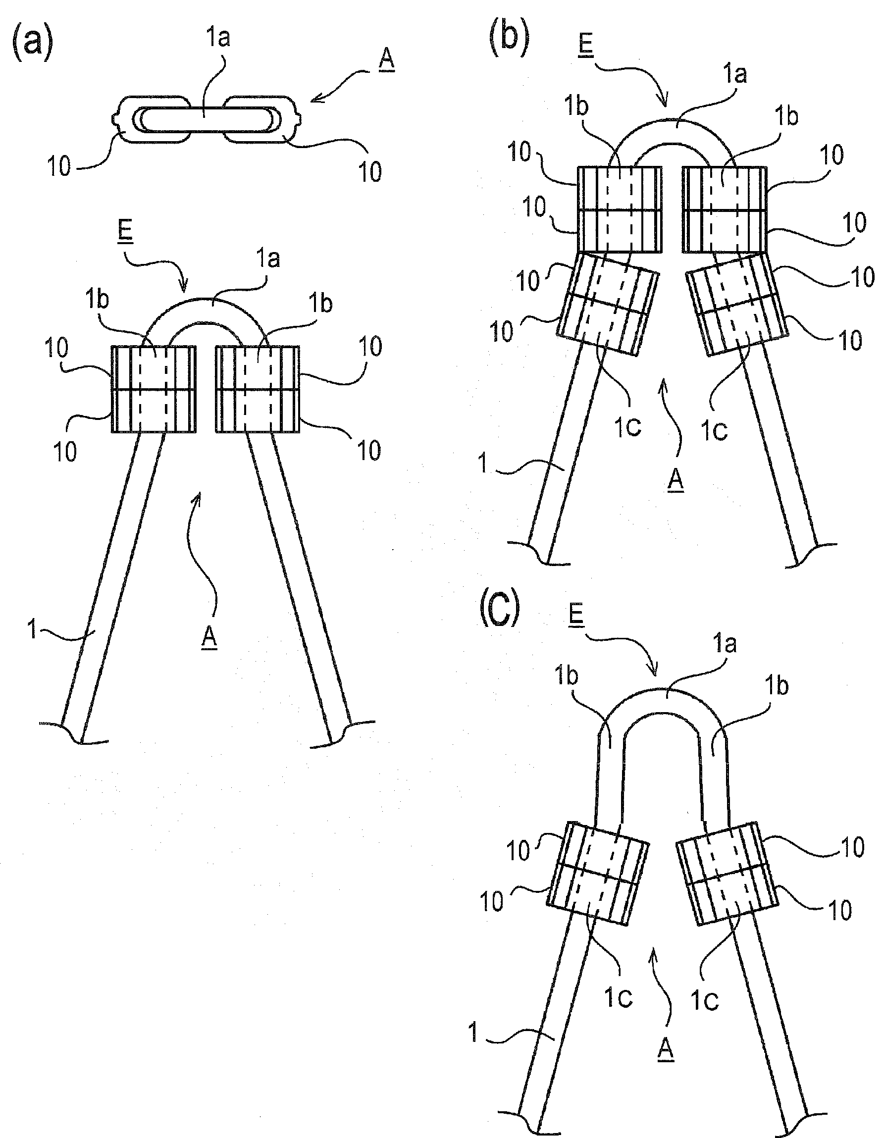
[0061] Next, the structure of the marker and the stent provided with the marker according to the first embodiment will be described using the drawings. figure 1 It is a figure explaining the structure of the marker concerning 1st Example. figure 2 It is a figure explaining the structure of a bracket.
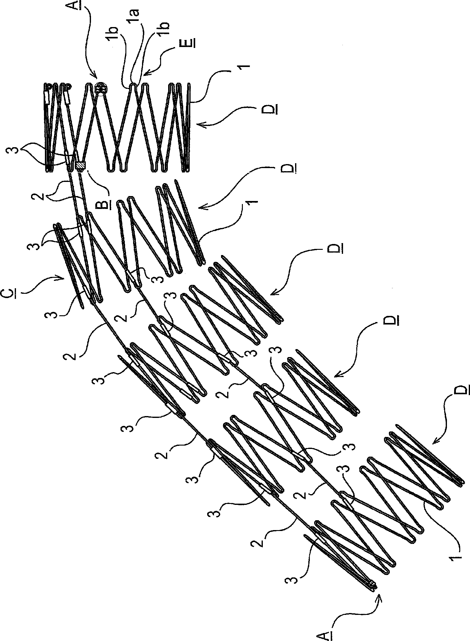
[0062] First, use figure 2 The overall structure of the bracket C will be described. The stent C is constructed by connecting a plurality (five in this embodiment) of ring stents D formed by forming the stent main wire 1 in a zigzag shape and welding the ends via struts 2 .
[0063] For the stent main wire 1 constituting the ring stent D, a wire material of SUS316L, which is generally provided as austenitic stainless steel, especially stainless steel for transplantation, is used. In addition, the wire rod is cold-drawn to elongate the structure into a fibrous shape, whereby the wire rod is work-hardened and mechanical properties are improved. By constituting the ring stent...
Embodiment 2
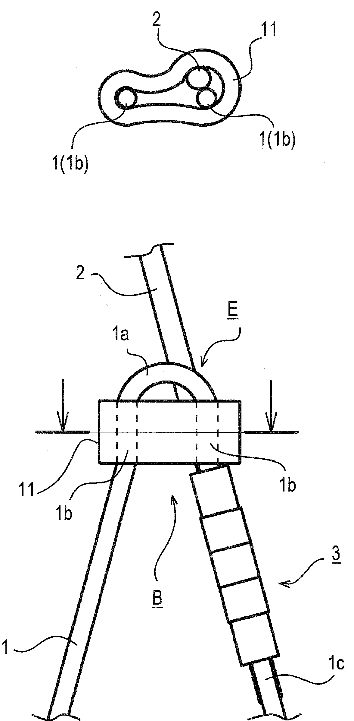
[0080] Next, the structure of the marker according to the second embodiment will be described using the drawings. image 3 It is a figure explaining the structure of the marker B concerning 2nd Example.
[0081] The marker B involved in this embodiment is constituted by fastening the tube 11 embedded in two stent main wires that are close to each other at the foldback portion E of the straddling stent D. In addition, the tube 11 used in this Example is comprised using SUS316L as a material similarly to the said Example.
[0082] image 3 The shown pipe 11 is fitted to the two stent main wires 1 that are close to the ring stent D at the foldback portion E from the outside of the ring stent D across the two stent main wires 1 . In addition, the tube 11 is fastened at a position corresponding to the parallel portion 1b of the two stent main wires 1 at the folded portion E, thereby constituting the marker B.
[0083] The marker B as described above is configured by fastening th...
Embodiment 3
[0093] Next, the structure of the marker B according to the third embodiment will be described using the drawings. Figure 4 It is a figure explaining the marker provided in the attachment part of the stabilizer hook arrange|positioned at the front-end|tip part of a bracket. In addition, in this Example, the hook 4 for stabilizers is used instead of the support|pillar 2, The structure is the same as the said 2nd Example other than that. Therefore, the same reference numerals are assigned to the same parts as those in the second embodiment, and description thereof will be omitted.
[0094] The stabilizer hook 4 is arranged at the front end of the stent C, and is used to engage with the periphery of the target affected area when the stent C is placed on the target affected area. The stabilizer hook 4 does not act on the force of the strut 2 described above, so its diameter (about 0.45 mm) is the same as or smaller than the diameter of the stent main wire 1 .
[0095] In additi...
PUM
 Abstract
Description
Claims
Application Information
 - R&D
- Intellectual Property
- Life Sciences
- Materials
- Tech Scout
- Unparalleled Data Quality
- Higher Quality Content
- 60% Fewer Hallucinations
Browse by: Latest US Patents, China's latest patents, Technical Efficacy Thesaurus, Application Domain, Technology Topic, Popular Technical Reports.
© 2025 PatSnap. All rights reserved.Legal|Privacy policy|Modern Slavery Act Transparency Statement|Sitemap|About US| Contact US: help@patsnap.com


