Power control system and method and program for controlling power control system

A power control system and power control technology, applied in the direction of power network operating system integration, information technology support systems, electrical components, etc., can solve problems such as temperature rise, switch-on or setting temperature change, microwave discharge start, etc., and achieve a low-cost structure , the effect of saving time and energy

Inactive Publication Date: 2012-02-01
PANASONIC CORP
View PDF10 Cites 37 Cited by
  • Summary
  • Abstract
  • Description
  • Claims
  • Application Information

AI Technical Summary

Problems solved by technology

For example, there are phenomena such as power-on or set temperature rise when using an iron, power-on or set temperature change when using an air conditioner, or power-on or internal microwave discharge start when using a microwave oven, etc.

Method used


Image

  • Power control system and method and program for controlling power control system
  • Power control system and method and program for controlling power control system
  • Power control system and method and program for controlling power control system

Examples


no. 1 example

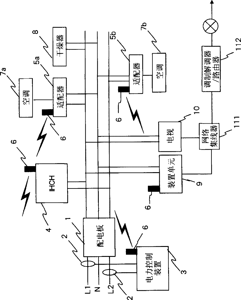
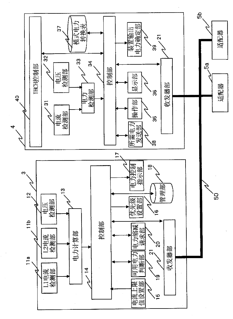
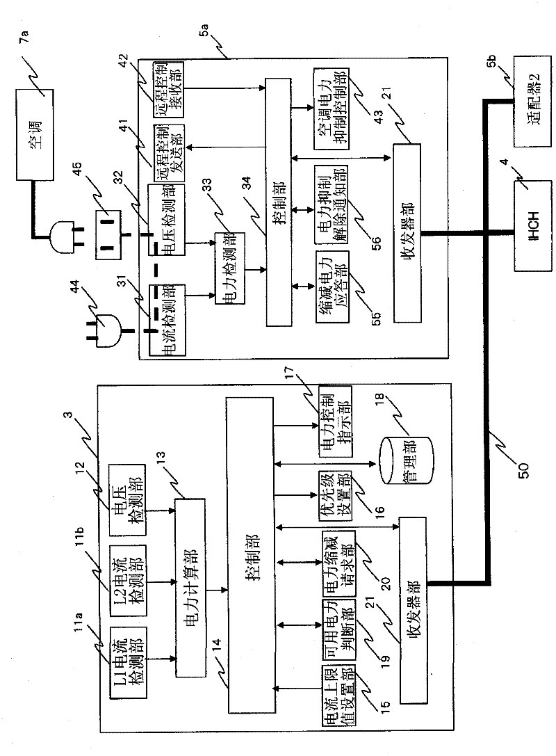
[0062] figure 1 is a diagram showing the system configuration of the power control system of the present invention, figure 2 is a block diagram showing a power control device and an IH cooking heater of a power control system, and image 3 It is a block diagram showing an adapter connected to the power control device of the power control system and the air conditioner.

[0063] In the first embodiment of the present invention, a current clamp 2 is provided on the power line at the input side of the distribution board 1 for introducing single-phase three-wire type 200V into the home, and the power control device 3 measures the input current L1 and L2.

[0064] In addition, the output line of the distribution board is connected with the following devices: IH cooking heater 4 as AC 200V system; dryer 8 in L1 phase as AC 100V system and adapter 5a connected with air conditioner 7a and in L2 phase The adapter 5b to which the air conditioner 7b; and the device unit 9 and the te...

no. 2 example

[0130] will refer to Figure 8 The structure of the second embodiment of the present invention will be described. exist Figure 8In , reference numeral 61 denotes a first home appliance, and it is assumed that the first home appliance 61 has a higher priority than the second home appliance 70 and the third home appliance 71 when using electric power. In addition, reference numeral 62 denotes a power detection section, and the power detection section 62 measures the power used by the first home appliance 61 and outputs the power as a power information signal. Reference numeral 65 denotes a home appliance control section, and inputs the electric power information signal detected by the electric power detection section 62 and the home appliance control signal acquired by the home appliance information communication section 64 to the home appliance control section 65 . The home appliance control section 65 outputs a control signal based on the power information signal and the ho...


PUM


Abstract

When a user wants to operate a device, if electric power is being used at a level such that a circuit breaker will shut off, he cannot use the device he wants to use unless he himself intentionally reduces the electric power being used for the other devices to increase the amount of usable power. A power control device (3) is provided with a priority setting unit (16) that is capable of setting usage priorities for household devices connected by wire or wirelessly or for adaptors connected to the household devices. A household device or an adaptor connected to the household device operates within the usable power resulting from an inquiry to the power control device (3). When there is no excess in usable power over the power required in the inquiry, the power control device (3) reduces the power used by a device which has a lower priority than the device which made the inquiry in order to allow the device with the higher priority to be used.

Description

technical field [0001] The present invention relates to a control method and a program of a power control system configured to control devices so as to prevent a situation in which a current limiter of a home main power line operates due to an overcurrent, thereby Cut off the power to the device in use. Background technique [0002] In an example of such a power control system, a device requests a use permission from a circuit breaker device when used, and the circuit breaker device judges whether the use is permitted, and the device operates within the power permitted by the circuit breaker device (for example, see Patent Document 1). [0003] Figure 14 is a configuration diagram of a conventional power control system disclosed in Patent Document 1, and Figure 15 is a flowchart showing the processing operation of the device. [0004] exist Figure 14 , the power line network includes a circuit breaker device 101 , a power line 102 , sockets 103A-103D, devices 104-106 a...

Claims


Application Information

Patent Timeline
Patent Type & Authority Applications(China)
IPC IPC(8): H02J13/00H02J3/00H04Q9/00
CPCH02J2003/143Y02B70/3266Y04S20/222Y02B90/2653Y02B70/3225H02J13/0075H02J3/14Y04S40/126Y04S20/242H02J2310/14H02J13/00004H02J13/00034Y02B70/30Y02B90/20H02J13/00022
Inventor 甲田哲也栗本和典辻村敏中谷直史吉村康男
Owner PANASONIC CORP
Why Eureka
Try Eureka