Sealing ring structure for high-flow high-lift double suction pump

A sealing ring and high-lift technology, which is applied to components, pumps, and pump components of elastic fluid pumping devices, can solve the problems of reducing the actual flow rate of the pump, reducing efficiency, increasing hydraulic loss, etc., and achieve volume reduction Effects of loss, life extension, and leakage reduction

Inactive Publication Date: 2012-02-08
SHANGHAI KAIQUAN PUMP IND GROUP
View PDF0 Cites 4 Cited by
  • Summary
  • Abstract
  • Description
  • Claims
  • Application Information

AI Technical Summary

Problems solved by technology

During the operation of the pump, especially the double-suction pump with large flow rate and high head, due to improper processing, natural wear, solid particles in the medium, impeller shaking, etc., the radial gap between the impeller mouth ring and the sealing ring of the centrifugal pump becomes larger, Or the phenomenon of seal ring rupture; especially when the medium pumped by a large-flow high-lift double-suction pump contains solid particles or corrosive substances, the strong hydraulic impact directly erodes the "watershed" of the shell (that is, the gap between the suction chamber and the high-pressure chamber). The casting segment between the castings), resulting in the phenomenon of water stringing in the high and low pressure chambers; then, the sealing effect cannot be achieved, causing a large amount of backflow, reducing the actual flow rate of the pump, increasing the volume loss, and causing the liquid to form a vortex at the impeller inlet, making the suction Poor performance, increased hydraulic losses, reduced efficiency

Method used


Image

  • Sealing ring structure for high-flow high-lift double suction pump
  • Sealing ring structure for high-flow high-lift double suction pump
  • Sealing ring structure for high-flow high-lift double suction pump

Examples


Embodiment Construction

[0011] Below in conjunction with accompanying drawing and specific embodiment the present invention is described in further detail:

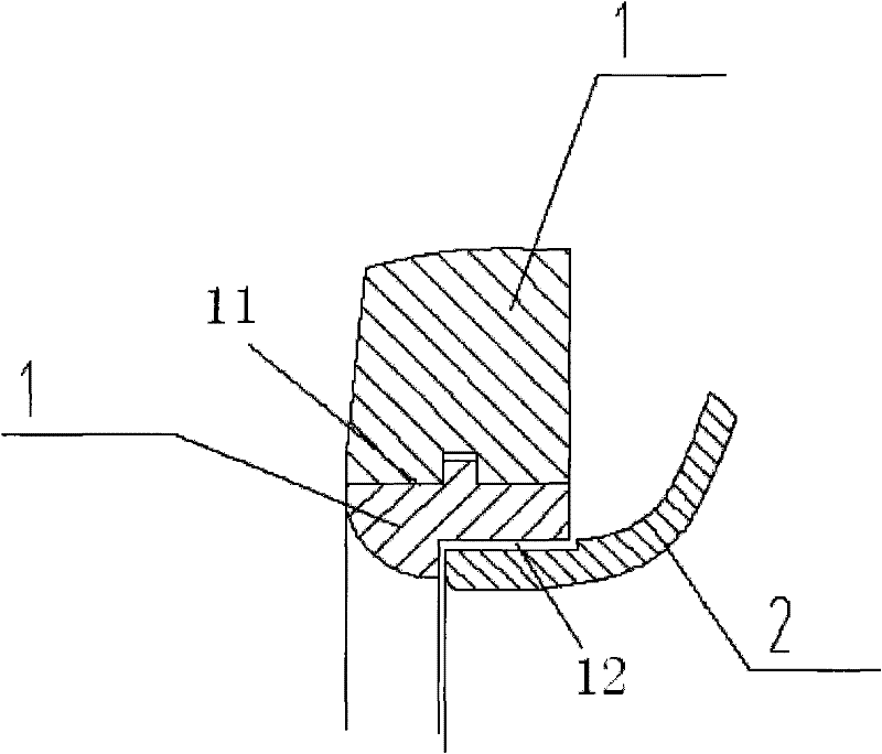
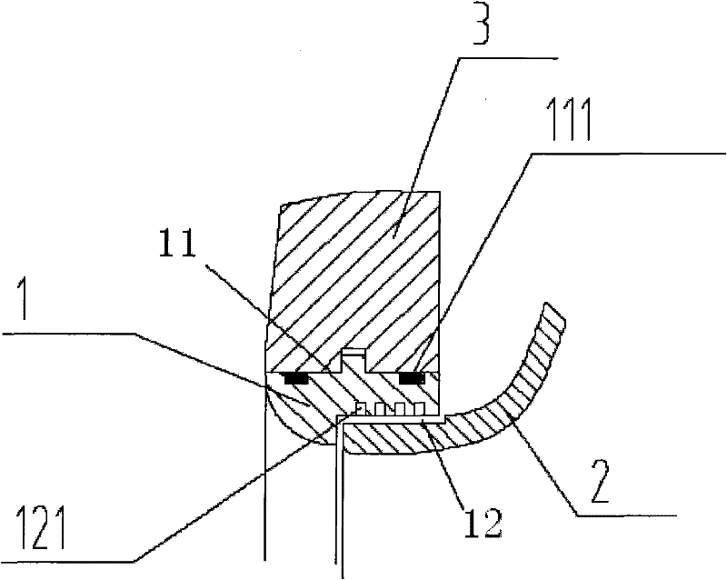
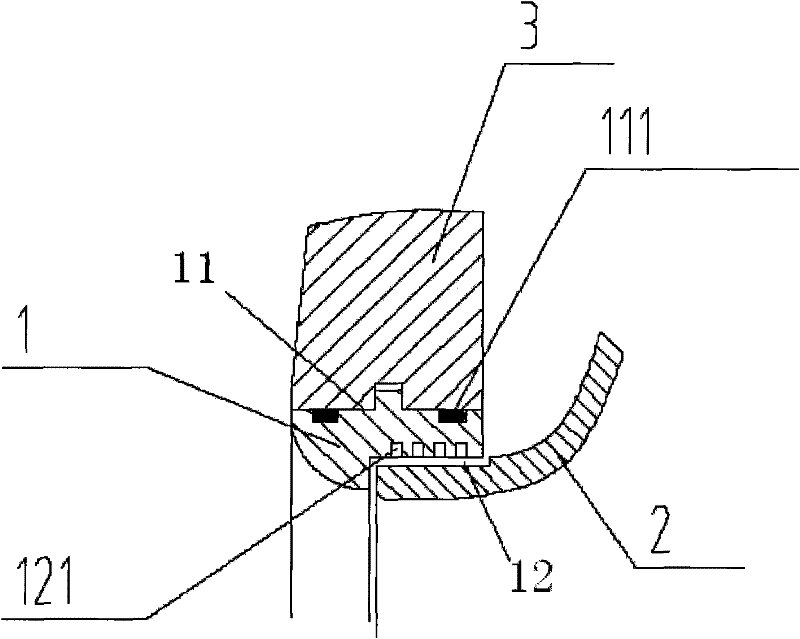
[0012] Depend on figure 2 It can be seen that the present invention includes: a body 1; the body 1 includes a sealing ring outer circle 11 and a sealing ring inner circle 12; (shown) two O-rings 111 matched with the mating surface; at least 3 labyrinth seal grooves 121 matched with the notch of the impeller 2 are also arranged on the inner circle 12 of the sealing ring;

[0013] The size of the sealing groove 121 is between 5-7mm. In the figure: housing 3.

[0014] The present invention adds two O-rings on the outer circle of the sealing ring (matching with the pump body and pump cover), and adds a labyrinth sealing groove on the inner circle of the sealing ring (matching with the impeller seam). The size of the labyrinth sealing groove (5 -7mm) and the number (≥3) are designed according to the actual situation.

[0015] The change of the s...


PUM


Abstract

The invention relates to a sealing ring structure for a high-flow high-lift double suction pump. The structure comprises a body, wherein the body comprises a sealing ring outer circle and a sealing ring inner circle; the sealing ring outer circle is provided with two O-rings matched with matching surfaces of a pump body and a pump cover; and the sealing ring inner circle is provided with at least three labyrinth seal grooves matched with a seam allowance position of an impeller. The sealing ring structure has the advantages that: A, through the labyrinth seal grooves, the leakage rate of liquid which returns from an impeller outlet (a high-pressure cavity) to an impeller inlet (a low-pressure cavity) is well reduced, volume loss is reduced, the efficiency of the pump is improved, and energy is well saved; B, the O-rings of the outer circle are used, so that water in the high-pressure cavity and water in the low-pressure cavity of a water pump are prevented from being mixed with each other, and washout caused by hydraulic impact of the liquid from the impeller outlet (the high-pressure cavity) to one side of the impeller inlet (the low-pressure cavity) is avoided; and C, a sealing ring is easy to manufacture, reliably installed and low in cost, and the service life is prolonged.

Description

technical field [0001] The invention relates to a sealing ring of a double-suction pump with a large flow rate and a high lift, in particular to the structure of the sealing ring. Background technique [0002] In the prior art, the sealing ring structure used in the large-flow high-lift double-suction pump generally adopts a straight and simple structure (such as figure 1 Shown, among the figure housing 3, impeller 2), promptly the inner and outer circle (12,11) places of sealing ring 1 are all straight faces. During the operation of the pump, especially the double-suction pump with large flow rate and high head, due to improper processing, natural wear, solid particles in the medium, impeller shaking, etc., the radial gap between the impeller mouth ring and the sealing ring of the centrifugal pump becomes larger, Or the phenomenon of seal ring rupture; especially when the medium pumped by a large-flow high-lift double-suction pump contains solid particles or corrosive subs...

Claims


Application Information

Patent Timeline
Patent Type & Authority Applications(China)
IPC IPC(8): F04D29/16
Inventor 邓帮华张月瑛尹卫东
Owner SHANGHAI KAIQUAN PUMP IND GROUP
Why Eureka
Try Eureka