Method for detecting initial magnetic field position of linear synchronous motor

A technology of motor position and detection method, applied in the direction of electronic commutator, etc., can solve the problems of electrical angle deviation, large calculation error, large software calculation amount, etc., to avoid a large number of calculations, improve detection accuracy and fast detection Effect

Inactive Publication Date: 2012-02-08
上海开通数控有限公司
View PDF0 Cites 4 Cited by
  • Summary
  • Abstract
  • Description
  • Claims
  • Application Information

AI Technical Summary

Problems solved by technology

In this detection method, the software in the microprocessor of the servo controller has a large amount of calculation and the calculation is complicated, which affects the control speed of the servo controller, and because the motor three-phase pulse signal and zero pulse of the photoelectric encoder are used for detection, the calculated The error is large because there are 6 states within the 360° electrical angle of the motor, so the electrical angle deviation of each phase is plus or minus 30°

Method used


Image

  • Method for detecting initial magnetic field position of linear synchronous motor
  • Method for detecting initial magnetic field position of linear synchronous motor

Examples


Embodiment Construction

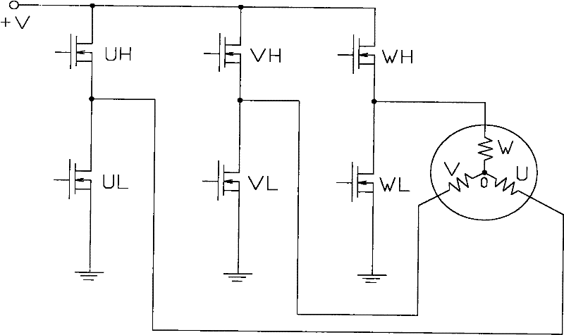
[0010] like figure 1 As shown, the method for detecting the initial magnetic field position of a linear synchronous motor of the present invention includes a motor controlled by a three-phase inverter of a servo controller and an incremental photoelectric encoder for detecting the position of the motor. The three-phase winding of the motor U , V and W are connected at one end, and the other ends of the three-phase windings U, V and W of the motor are respectively connected between the upper and lower arms of the U-phase, V-phase and W-phase of the three-phase inverter, and the system is powered on. The servo controller controls the three-phase inverter V-phase upper arm VH and W-phase lower arm WL to conduct, and the remaining bridge arms UH, UL, VL, and WH are turned off. At this time, the current flows through the V-phase upper arm VH, Motor V-phase winding V, motor W-phase winding W, W-phase lower bridge arm WL, taking the common terminal O of the motor three-phase winding ...


PUM


Abstract

The invention discloses a method for detecting an initial magnetic field position of a linear synchronous motor. A motor is controlled by using a three-phase inverter of a servo controller; a system is electrified; under the control of the servo controller, a V-phase upper bridge arm and a W-phase lower bridge arm of the three-phase inverter are conducted, and other bridge arms are cut off; at the moment, a current sequentially flows through the V-phase upper bridge arm, a V-phase winding of the motor, a W-phase winding of the motor and the W-phase lower bridge arm; by using common ends of three-phase windings of the motor as reference points, a positive current flows through the V-phase winding of the motor, and a negative current flows through the W-phase winding of the motor; and after the motor stops rotating, the servo controller acquires a motor position signal which is fed back by an incremental photoelectric coder, and a motor position serves as the initial magnetic field position of the motor. By adoption of the method, the initial magnetic field position of the motor can be simply, conveniently and quickly detected, a large amount of calculation of a microprocessor of the servo controller is avoided, and detection accuracy and the control speed of the servo controller are improved.

Description

technical field [0001] The invention relates to a method for detecting the initial magnetic field position of a linear synchronous motor. Background technique [0002] The position detection of the motor is very important in motor control, especially in applications that need to control the motion state of the motor according to the precise rotor position, such as position servo systems, such as figure 1 As shown, the motor is controlled by the three-phase inverter of the servo controller, one end of the three-phase winding of the motor is connected, and the other end is connected between the upper bridge arm and the lower bridge arm of the three-phase inverter respectively. The traditional motor position detection method is generally calculated based on the feedback signal of the incremental photoelectric encoder installed on the motor shaft. The incremental photoelectric encoder indicates the position information of the motor rotor connected to the incremental photoelectr...

Claims


Application Information

Patent Timeline
Patent Type & Authority Applications(China)
IPC IPC(8): H02P6/16
Inventor 郭凤仙方杰
Owner 上海开通数控有限公司
Why Eureka
Try Eureka