Pneumatic steel wire gauze gun

A steel mesh and pneumatic technology, applied in the field of clamps, can solve the problems of short continuous power supply time, low efficiency and short service life of rechargeable batteries

Active Publication Date: 2012-02-15
GUANGDONG MINGHUI PNEUMATIC TECH CO LTD
View PDF4 Cites 30 Cited by
  • Summary
  • Abstract
  • Description
  • Claims
  • Application Information

AI Technical Summary

Problems solved by technology

[0003] At present, there are no relevant stereotyped products on the market, only self-made modified manual or electro-hydraulic pliers are used in production activities
Moreover, the efficiency is low, the mobile operation is very inflexible, and the outdoor operation is highly restrictive. It is difficult to achieve unified technical instructions for finished products, and the quality is uneven.
The use of human mechanical transmission clamps is time-consuming and labor-intensive, with high labor intensity and low efficiency for operators; although human hydraulic transmission clamps are easy to use, they are also time-consuming, laborious, heavy, and prone to oil leakage; electro-hydraulic transmission clamps are used The lower end of the housing is powered by a rechargeable battery fixed in the battery box, and the motor drives the pliers to press together, so that the metal clip nails put in the pliers are bent and rolled. The electro-hydraulic transmission pliers are easy to operate, but during use It is found that the continuous power supply time of the rechargeable battery is short, the charging time of the clamp is long, and the price of the rechargeable battery is high, and the service life is short. Therefore, the rechargeable battery cannot meet the needs of long-term work, and the disadvantages are particularly prominent in field operations.
Have again, when above-mentioned tongs are operated, all are by first putting metal clip nails on the pliers mouth, pressing one, then putting in the second metal clip nails, repeating the above operations, such an operation mode does not Fundamentally solve the shortcomings of heavy labor and long time consumption; during the operation of manual assembly of metal clip nails, workers will accidentally pinch their fingers from time to time, and there is a certain degree of danger in the operation process

Method used


Image

  • Pneumatic steel wire gauze gun
  • Pneumatic steel wire gauze gun
  • Pneumatic steel wire gauze gun

Examples


Embodiment Construction

[0030] The invention will be described in further detail below in conjunction with the accompanying drawings.

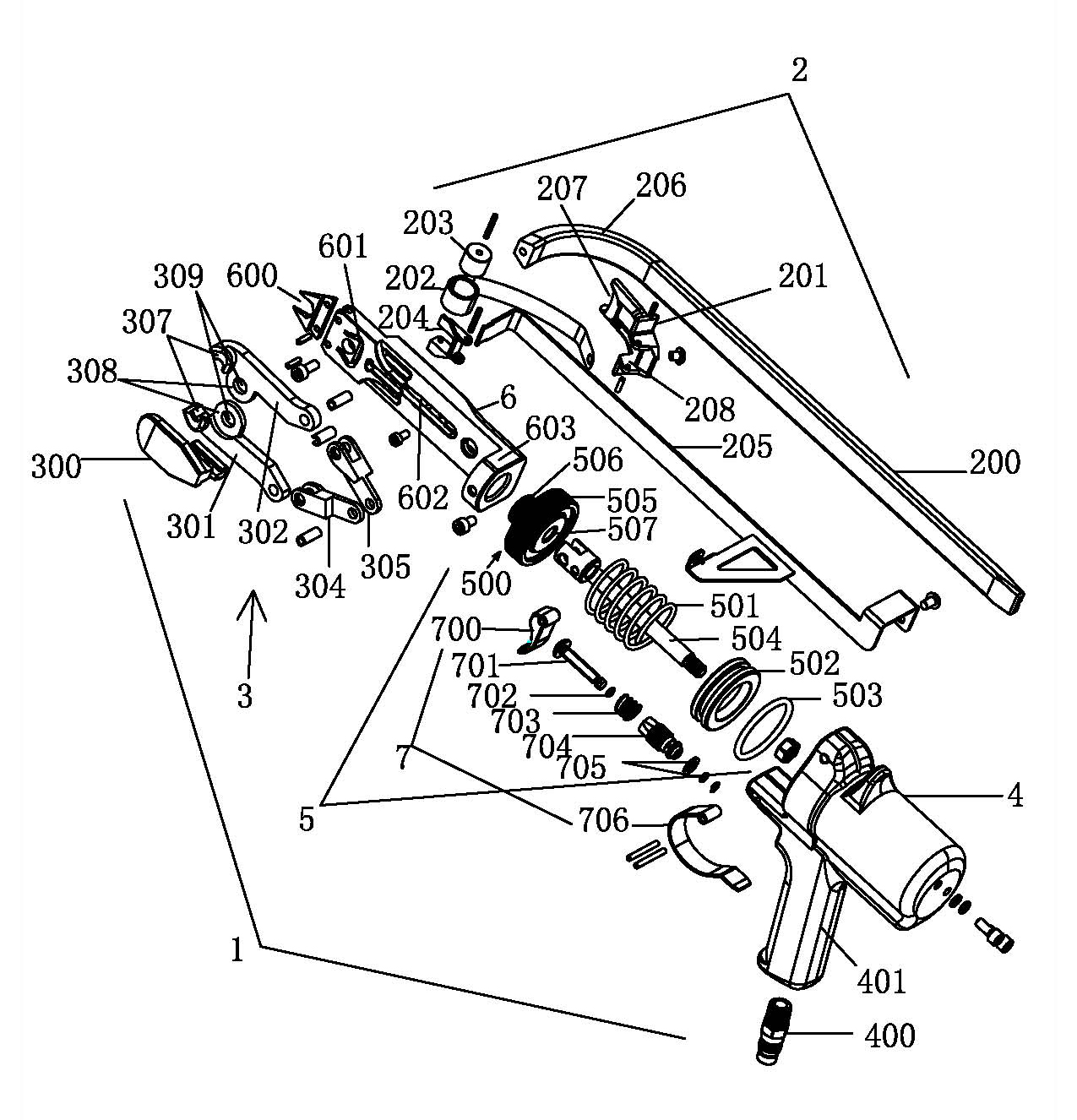
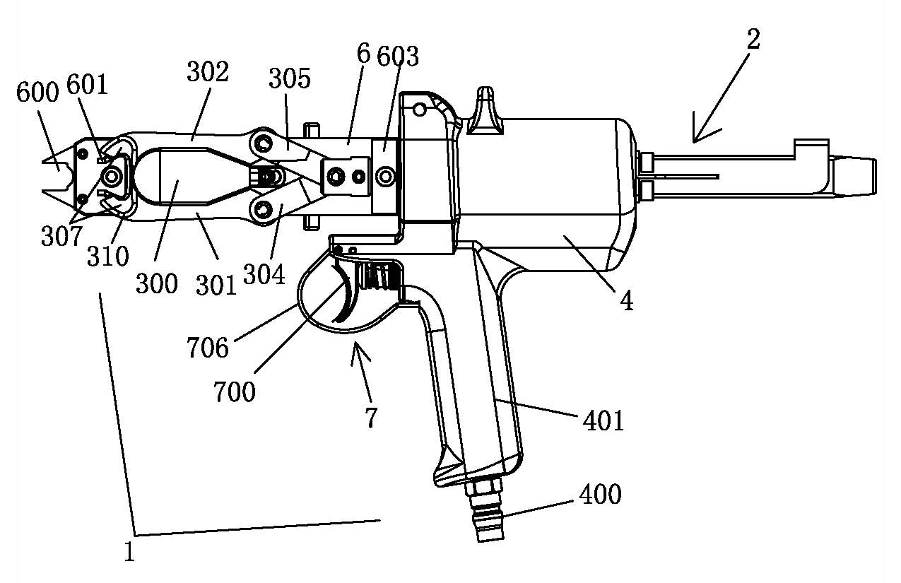
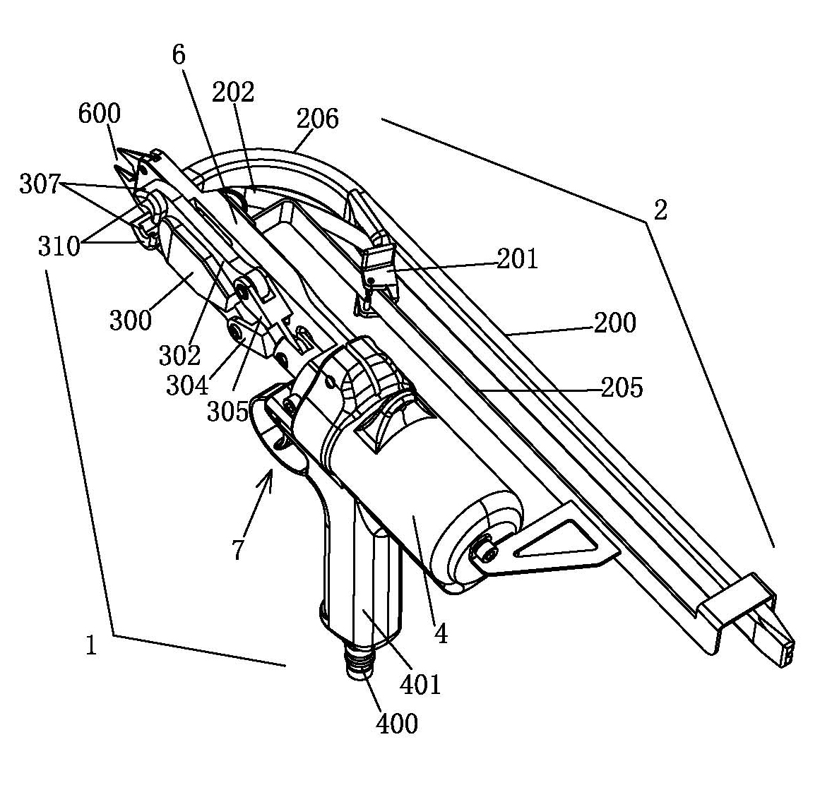
[0031] Such as Figure 1 to Figure 7 As shown, a pneumatic wire mesh gun 1 includes a clamp gun 1 and a nail box 2 .

[0032] Such as Figures 1 to 3 As shown, the clamp gun 1 is mainly composed of a gun frame 6, a gun body 4, a cylinder 5 and a clamp assembly 3 installed on the gun frame 6; the gun body 4 is provided with an air intake chamber, and the cylinder 5 is installed in the air intake chamber , the air intake pipe joint 400 of the air intake chamber stretches out of the gun body 4, and the gun body 4 is also equipped with a switch assembly 7 for controlling the opening or closing of the air intake pipe joint 400. The rear end is provided with the connection block 603 of screw hole, has guide groove 602 on the surface of gun frame 6, and the rear end of gun frame 6 is connected with the cylinder 5 front end that is installed in the gun body 4, and the pist...


PUM


Abstract

The invention relates to a pneumatic steel wire gauze gun. The pneumatic steel wire gauze gun provided by the invention comprises a pincers gun and a nail box, wherein the coiled spring of the nail box pulls back a nail feeder by installing the nail box at one side of a gun rack, so that a metal clamping slice nail is automatically delivered into a pincers mouth of the pneumatic steel wire gauze gun; a piston rod of a cylinder simultaneously pushes the rear ends of left and right connecting rods, and forces are transmitted to left and right clamping jaws at the front ends of the left and right connecting rods so as to drive a sliding block to slide forwards along a guide slot of the gun rack; when the front end of the sliding block abuts against the front end of the guide slot, the sliding block stops sliding; the rear ends of the left and right clamping jaws are pushed by the forces to stretch by taking the hinge pin of the sliding block as the fulcrum, so that pincers mouths of the left and right clamping jaws are closed, and the metal clamping slice nails arranged in the pincers mouths are pressed to be rolled. The pneumatic steel wire gauze gun provided by the invention has the advantages of automatic nail delivery, convenience in operation, time and labor conservation and high safety.

Description

technical field [0001] The invention relates to the technical field of clamps, in particular to a pneumatic wire mesh gun. Background technique [0002] Metal wire clamps are mainly used for the purpose of binding two or more wire (wire) materials (such as steel wire, steel wire rope, nylon rope and other metal or non-metallic wires) together. nails, and then press the metal clip nails to bind the silk (wire) materials together, or press two or more disjoint metal wires with the clamps to press the metal clip nails to make the metal wires The joints are spliced ​​together, and the splicing is firm. The materials such as steel wire ropes are processed into finished products to meet the requirements of use. The finished products of the target materials can be used in many fields, such as steel wire mesh for hillside retaining walls, cages for mariculture, Chicken cages and animal cages for poultry breeding industry, pasture fences, products used in military industry, such as ...

Claims


Application Information

Patent Timeline
Patent Type & Authority Applications(China)
IPC IPC(8): B21F27/08
CPCB25F5/02B21F27/08
Inventor 林岳洪
Owner GUANGDONG MINGHUI PNEUMATIC TECH CO LTD
Why Eureka
Try Eureka