Fireplace for vaporizing combustion of liquid fuel

A liquid fuel and fireplace technology, which is applied in the direction of gas fuel burners, liquid heating fuel, liquid fuel supply/distribution, etc., can solve the problems of ineffective control of liquid fuel combustion, insufficient liquid fuel combustion, and low combustion efficiency, etc., to achieve Miniaturized overall structure design, clean fuel combustion, and simplified gasification process

Active Publication Date: 2012-02-15
NINGBO RICHEN ELECTRIC APPLIANCE CO LTD
View PDF9 Cites 17 Cited by
  • Summary
  • Abstract
  • Description
  • Claims
  • Application Information

AI Technical Summary

Problems solved by technology

The fireplaces of the above two patents all use liquid fuel for fuel, but the liquid fuel in the two patents uses the direct combustion of liquid fuel when burning, which not only makes the combustion of the liquid fuel insufficient and the combustion efficiency is low , and cannot effectively control the combustion of liquid fuel
Gasification of liquid fuel and then combustion can make the fuel have the advantages of low temperature, easy combustion control and good combustion flame. In order to improve the combustion efficiency of liquid fuel, people use the method of gasifying liquid fuel to realize the combustion of liquid fuel , but the structure of the current liquid fuel gasification device is relatively complicated, and it must first be preheated by igniting the fuel in the preheating combustion cup. During the ignition process, the liquid fuel is usually exposed to the air, and there is still a certain degree of safety Hidden danger

Method used


Image

  • Fireplace for vaporizing combustion of liquid fuel
  • Fireplace for vaporizing combustion of liquid fuel
  • Fireplace for vaporizing combustion of liquid fuel

Examples


Embodiment 1

[0024] Embodiment one, such as Figure 1 ~ Figure 4 Shown:

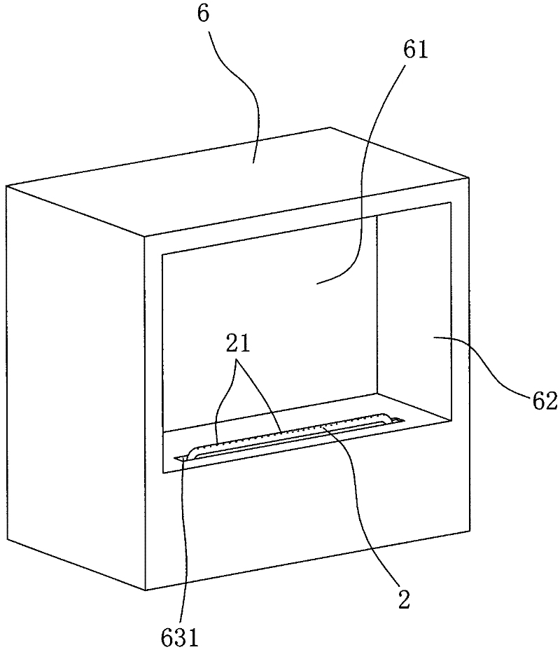
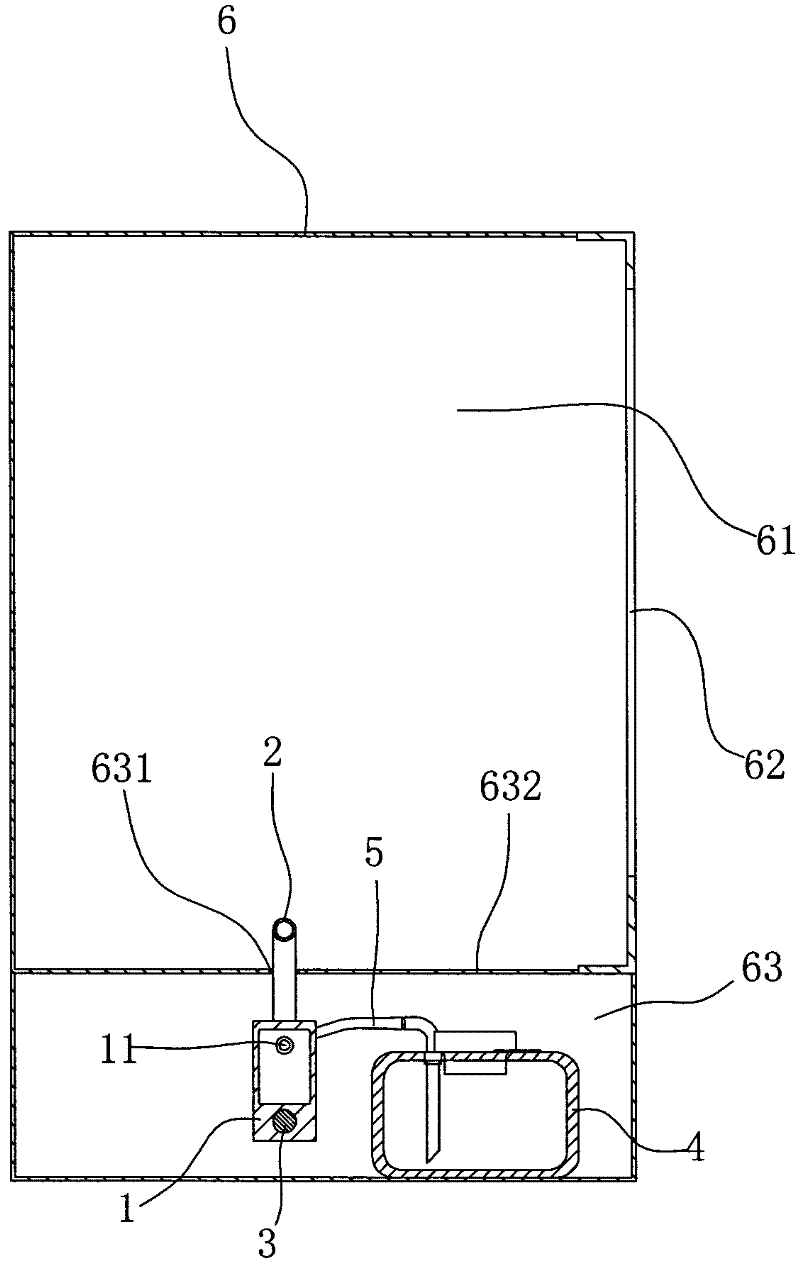
[0025] This embodiment is a fireplace that adopts gasification and combustion of liquid fuel. The fireplace includes a furnace body 6, a furnace chamber 61 is provided inside the furnace body 6, and a flame observation port that communicates with the furnace chamber 61 is also provided at the front of the furnace body 6. 62, and the furnace body 6 also forms a chamber 63 at the bottom of the furnace cavity 62, and a combustion device for gasification and combustion of liquid fuel is placed in the chamber 63;

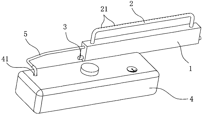
[0026] The combustion device includes a gasification chamber 1, a burner 2, an electric heating device 3, a liquid fuel tank 4 and a feed pipe 5, wherein the top surface 632 of the chamber 63 is provided with a slot 631, and the burner just passes through the slot The hole 631 is exposed in the furnace cavity 61, the side of the gasification chamber 1 is provided with a liquid fuel addition port 11, the side w...

Embodiment 2

[0031] Embodiment two, such as Figure 5 ~ Figure 7 as shown,

[0032] The fireplace in the second embodiment includes a furnace body 9', a furnace cavity 91' is opened inside the furnace body 9', a detachable furnace door 92' is provided on the front of the furnace body 9', and a and The furnace chamber 91' is connected to the flame observation port 921', and the furnace body 9' forms a chamber 93' at the bottom of the furnace chamber 91', and a combustion device for gasification and combustion of liquid fuel is placed in the chamber 93';

[0033] The combustion device of the second embodiment also has a gasification chamber 1', a burner 2', an electric heating device 3', a liquid fuel tank 4' and a feed pipe 5', and between the liquid fuel tank 4' and the gasification chamber 1' Connected by the feed pipe 5', on the feed pipe 5' is also provided with an electromagnetic pump 51' to provide liquid fuel delivery power, the top of the liquid fuel tank 4' is provided with a liqu...


PUM


Abstract

The invention relates to a fireplace for vaporizing combustion of liquid fuel. The fireplace comprises a fireplace body, wherein a cavity which can accommodate a combustion device is formed at the bottom of a fireplace chamber in the fireplace body; and the front part of the fireplace body is provided with a flame viewing port. The fireplace is characterized in that: the combustion device comprises a liquid supply device, a vaporizing chamber and a combustor; the top of the cavity is provided with a slot hole for exposing the combustor; the combustor is provided with a flame jetting hole; the vaporizing chamber is provided with a liquid fuel inlet and a gas outlet; the liquid fuel inlet of the vaporizing chamber is communicated with the liquid supply device; the gas outlet of the vaporizing chamber is communicated with the combustor; the main body of the combustor is higher than a joint of the combustor and the vaporizing chamber; and the vaporizing chamber is also provided with an electrical heating device. The fireplace adopts a mode of the vaporizing combustion of the liquid fuel, is cleaner and more environment-friendly and has higher combustion efficiency; the vaporizing chamber is directly heated by the electrical heating device, and heat required by vaporizing the liquid fuel can be supplied without preheating; the whole structure is simpler; and the vaporizing process is simpler.

Description

technical field [0001] The invention relates to a fireplace, in particular to a fireplace that uses liquid fuel for gasification and combustion. Background technique [0002] Traditional fireplaces mostly use solid fuel for heating. Due to the large storage volume of solid fuel itself, the traditional fireplace occupies a large area, and has low combustion efficiency and poor energy-saving effect. [0003] With the continuous development of science and technology, liquid fuel has become a clean energy source with less pollution. It is lighter than solid fuel with the same heat energy and occupies less space. At the same time, it has the advantages of convenient storage and smaller pipelines than gas fuel. For example, the Chinese utility model "Convection Liquid Fireplace Heating Device" with the patent No. An automatic oil fired fireplace. The fireplaces of the above two patents all use liquid fuel for fuel, but the liquid fuel in the two patents uses the direct combustio...

Claims


Application Information

Patent Timeline
Patent Type & Authority Applications(China)
IPC IPC(8): F24D15/02
CPCF23K5/007F23K5/20F23K5/22F23D14/10F23D14/28F24C5/02F23D11/448F24B1/199
Inventor 周炜
Owner NINGBO RICHEN ELECTRIC APPLIANCE CO LTD
Why Eureka
Try Eureka