Resistor sampling isolation current detection circuit

The technology of a current detection circuit and a photoelectric isolation circuit is applied in the direction of voltage/current isolation, measuring current/voltage, measuring device, etc., and can solve problems such as narrow application range, charging of charging capacitor, and linear current sensor chip 21 without isolation function, etc. Achieve the effects of ensuring normal operation, wide range of applicable working conditions and improving reliability

Active Publication Date: 2012-02-15
TSINGHUA UNIV
View PDF5 Cites 14 Cited by
  • Summary
  • Abstract
  • Description
  • Claims
  • Application Information

AI Technical Summary

Problems solved by technology

In this case, the input voltage VEE cannot charge the charging capacitor C2 through the diode D1, and the linear current sensor chip 21 cannot work normally.
In high-voltage applications, in order to ensure the safety of electricity use, it is necessary to isolate the power circuit and the control circuit. However, the linear current sensor chip 21 has no isolation function, so its application range is narrow

Method used


Image

  • Resistor sampling isolation current detection circuit
  • Resistor sampling isolation current detection circuit
  • Resistor sampling isolation current detection circuit

Examples


Embodiment Construction

[0021]The present invention will be described in detail below in conjunction with the accompanying drawings and embodiments.

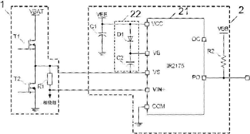
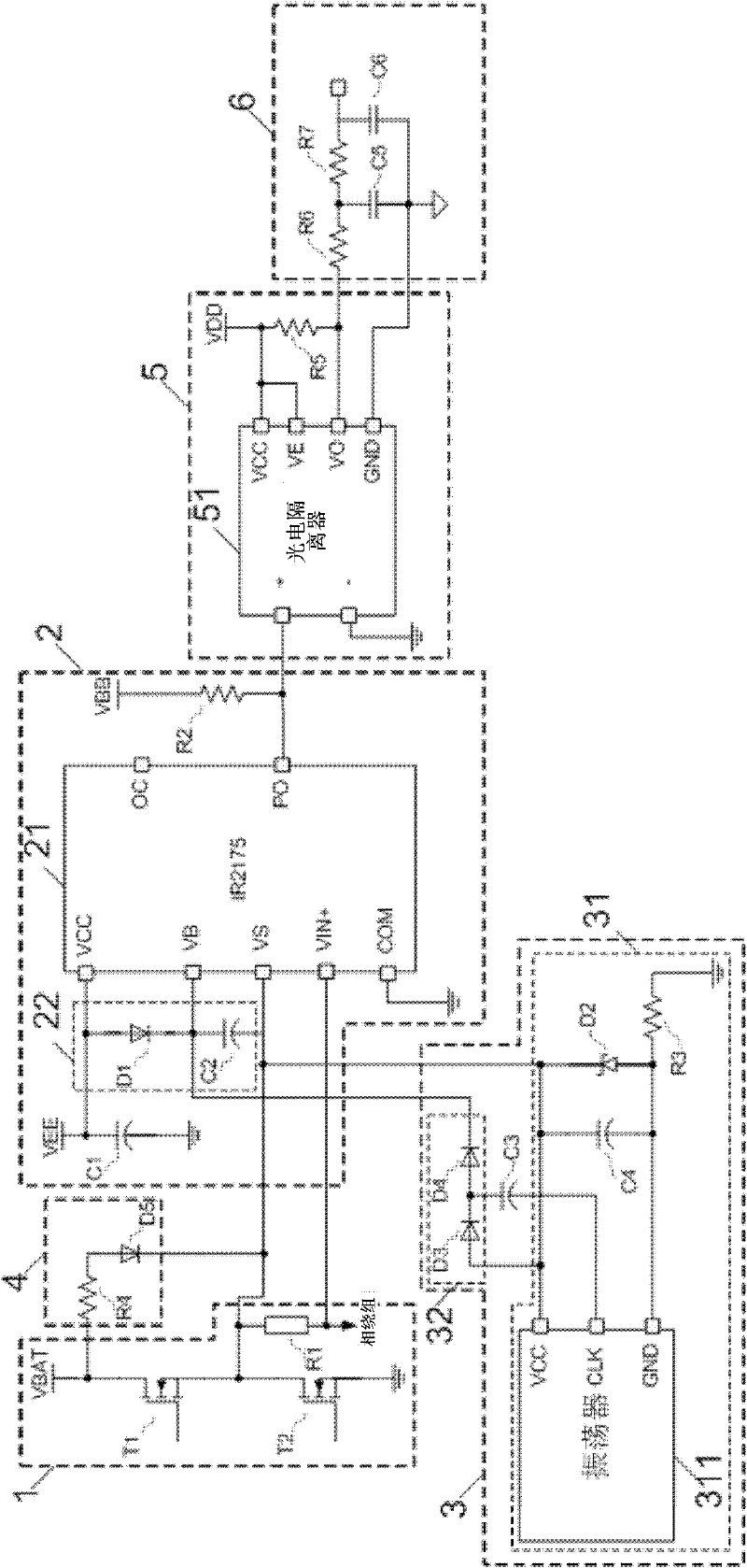
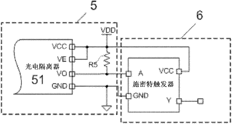
[0022] Such as figure 2 As shown, the present invention includes the same half-bridge circuit 1 and linear current sensor circuit 2 as the current detection circuit in the prior art, its structure and function are all the same as the current detection circuit in the prior art, and the half-bridge circuit 1 includes the upper bridge Transistor T1, lower bridge transistor T2 and sampling resistor R1; linear current sensor circuit 2 includes linear current sensor chip 21, bootstrap capacitor charging circuit 22, voltage stabilizing capacitor C1 and output pull-up resistor R2, wherein bootstrap capacitor charging circuit 22 is composed of Composed of diode D1 and charging capacitor C2. The present invention is characterized in that it also includes a charge pump circuit 3 , a charge pump start circuit 4 , a photoelectric isolation circuit 5 and a signal ...


PUM


Abstract

The invention relates to a resistor sampling isolation current detection circuit. The circuit comprises: a half-bridge circuit and a linear current sensor circuit. The half-bridge circuit comprises: an upper bridge transistor, a lower bridge transistor and a sampling resistor. The linear current sensor circuit comprises: a linear current sensor chip, a bootstrap capacitance charging circuit, a voltage stabilization capacitor and an output pullup resistor. The bootstrap capacitance charging circuit is formed by a diode and a charging capacitor. The current detection circuit of the invention also comprises: a charge pump circuit, a charge pump starting circuit, a photoelectric isolating circuit and a signal processing circuit. An output terminal of the charge pump circuit is respectively connected with a floating power supply terminal and a floating ground terminal of the linear current sensor chip. The charge pump starting circuit provides power for the charge pump circuit through the half-bridge circuit. An input terminal of the photoelectric isolating circuit is connected with the output terminal of the linear current sensor circuit. The output terminal of the photoelectric isolating circuit is connected with the output terminal of the signal processing circuit. After processing a signal, the signal processing circuit transmits the processed signal to a post-stage control circuit. The current detection circuit of the invention is suitable for detecting various kinds of half-bridge circuit currents in an electric power electron technology field.

Description

technical field [0001] The invention relates to a current detection circuit, in particular to a resistance sampling isolation current detection circuit used in a motor control system. Background technique [0002] In the motor control system, the controller needs to measure the current in the winding timely and accurately to realize the current closed-loop control and the design of the current protection circuit, so the current signal needs to be detected. Current detection must be real-time, accurate and reliable, and reliable isolation between the circuit under test and the control circuit is required in the high-voltage system. Usually the Hall current sensor and sampling resistor are used for current detection. The price of the Hall current sensor is relatively high. In some low-cost and low-power occasions, the application of sampling resistor is a good choice. The sampling resistor can directly convert the current signal of the main circuit into a voltage signal and s...

Claims


Application Information

Patent Timeline
Patent Type & Authority Applications(China)
IPC IPC(8): G01R19/00G01R15/22
Inventor 李建秋卢东斌欧阳明高谷靖
Owner TSINGHUA UNIV
Why Eureka
Try Eureka