Compact wastewater concentrator using waste heat

A concentrator and demister technology, applied in dehydration/drying/concentrated sludge treatment, heating water/sewage treatment, combustion type, etc., can solve problems such as corrosion, expensive exhaust gas, and increase the cost of structural support requirements, to achieve The effect of reasonable manufacturing and operating costs

Inactive Publication Date: 2012-02-15
HEARTLAND TECH PARTNERS
View PDF6 Cites 12 Cited by
  • Summary
  • Abstract
  • Description
  • Claims
  • Application Information

AI Technical Summary

Problems solved by technology

However, in order to capture and utilize the waste heat, extensive and expensive pipework and ductwork must be connected to the exhaust ducts to transfer the waste heat to where the treatment system is located, usually at ground level away from the building containing the generator
Importantly, the pipes, ductwork materials, and controls (e.g., throttle and shut-off valves) that can withstand the high temperatures (e.g., 1800 degrees Fahrenheit) of the exhaust gases in the exhaust pipe are very expensive and must be insulated during transport to retain the heat in the exhaust gas
Acceptable insulating materials suitable for the above purposes are often prone to failure due to various characteristics that add to the complexity of the design (e.g., brittleness, tendency to corrode over time, and susceptibility to thermal cycling)
Insulation adds weight to piping, ductwork materials, and controls, and also adds cost to structural support requirements

Method used


Image

  • Compact wastewater concentrator using waste heat
  • Compact wastewater concentrator using waste heat
  • Compact wastewater concentrator using waste heat

Examples


Embodiment Construction

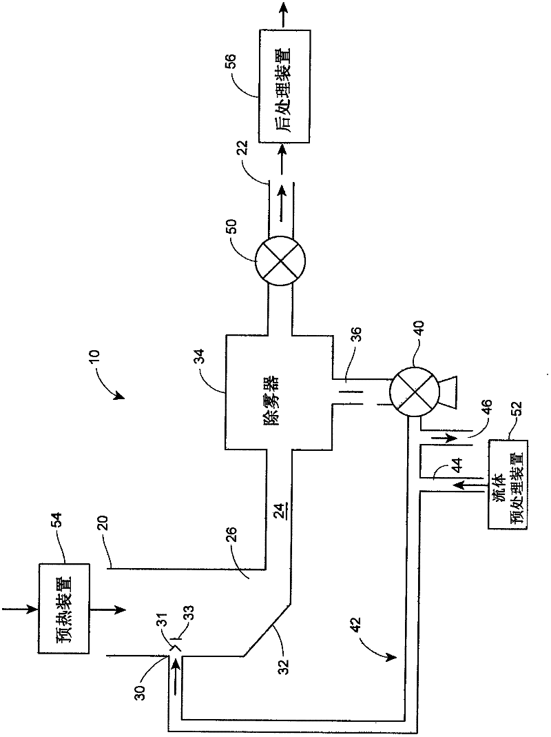
[0028] figure 1 An overall schematic view of the liquid concentrator 10 is shown, comprising a gas inlet 20 , a gas outlet 22 and a flow path 24 connecting the gas inlet 20 to the gas outlet 22 . Flow passage 24 includes a narrow portion 26 that accelerates gas flow through flow passage 24 , thereby creating turbulent flow within or near the narrow portion within flow passage 24 . In this embodiment, the narrow portion 26 is formed by a Venturi device. The liquid inlet 30 injects the liquid to be concentrated (by evaporation) into the liquid concentration chamber in the flow path 24 at a position upstream of the narrow portion 26 , and the injected liquid is combined with the gas flow in the flow path 24 . Liquid inlet 30 may include one or more replaceable nozzles 31 for spraying liquid into flow passage 24 . The liquid inlet 30 , whether equipped with a nozzle 31 or not, can inject liquid in any direction perpendicular or parallel to the gas flow as the gas passes through ...


PUM


Abstract

A compact and portable liquid concentrator includes a gas inlet, a gas exit and a flow corridor connecting the gas inlet and the gas exit, wherein the flow corridor includes a narrowed portion that accelerates the gas through the flow corridor. A liquid inlet injects liquid into the gas stream at a point prior to the narrowed portion so that the gas-liquid mixture is thoroughly mixed within the flow corridor, causing a portion of the liquid to be evaporated. A demister or fluid scrubber downstream of the narrowed portion removes entrained liquid droplets from the gas stream and re-circulates the removed liquid to the liquid inlet through a re-circulating circuit. Fresh liquid to be concentrated is also introduced into the re-circulating circuit at a rate sufficient to offset the amount of liquid evaporated in the flow corridor.

Description

technical field [0001] The present application relates generally to liquid concentrators and, more particularly, to compact, portable and inexpensive wastewater concentrators that can be easily connected to and utilize waste heat sources. Background technique [0002] Concentration of volatile species can be an effective form of treatment or pretreatment for various types of wastewater streams and can be performed in a variety of commercial treatment systems. Many highly concentrated wastewater streams can break down to residues in the form of slurries containing high concentrations of dissolved and suspended solids. This concentrated residue is readily solidified by conventional techniques for landfill disposal of residues, or may be suitable for sending to downstream processes for further processing prior to final disposal. Concentrating wastewater can greatly reduce transportation costs and required storage capacity, and can benefit downstream processes that recover mate...

Claims


Application Information

Patent Timeline
Patent Type & Authority Applications(China)
IPC IPC(8): C02F1/16C02F1/04C02F11/12
CPCB01D1/305C02F1/048C02F1/10C02F1/12C02F1/16C02F1/20C02F2201/008C02F2209/03Y02E20/12B01D1/14F23G7/085
Inventor 伯纳德·F·杜塞尔迈克尔·J·鲁奇克雷格·克雷尔金
Owner HEARTLAND TECH PARTNERS
Why Eureka
Try Eureka