In the gap coating machine head, the
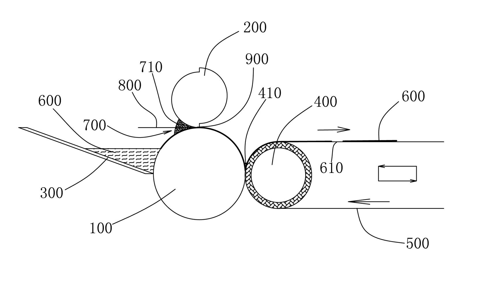
diameter of the driving roller 100 is constant, and its rotating speed is also constant. In order to minimize the influence of the accumulated material 700 on the thickness and uniformity of the slurry 600, it is necessary to make the accumulated material 700 as small as possible. It is far away from the coating gap 900. After research, it is found that the larger the diameter of the upper knife edge 200 of the comma type, the better the uniformity and accuracy of the cloth. However, the diameter of the upper knife edge 200 of the comma type cannot be made infinite. One is that the cost is not allowed, the other is that the installation space is not allowed; the third is that the diameter of the upper knife edge 200 of the comma type is too large, which will inevitably cause the weight of the upper knife edge to be too heavy, and it is difficult to adjust the coating of the upper knife edge 200 of the comma type and the driving roller 100 The gap is 900, which affects the uniformity of the thickness of the slurry on the pole piece; the fourth is that the comma type upper knife edge of 200 is too large, which is troublesome to make and the production cost is high
[0003] The traditional gap coating machine head still has the following problems. First, in order to realize the gap distribution, the back roller 400 is generally used to contact the driving roller 100 at intervals to realize the gap coating of the slurry 600. The driving roll 100 is in contact, and the slurry 600 is coated on the base foil 500; the back roll 400 is separated from the driving roll 100, leaving a slurry gap 610; In an instant, the back roller 400 is directly in contact with the slurry on the drive roller 100, and often the initial thickness of the slurry 600 is greater than the thickness when the drive roller 100 and the back roller 400 are in normal contact, which is called initial thickness in the industry; in addition, when After the back roller 400 is in contact with the driving roller 100 for a certain period of time, an accumulation 410 between the rollers will also be formed at the contact point between the two rollers. Phenomenon, the industry is called
tail length; the beginning thickness and
tail length will affect the quality of the pole piece
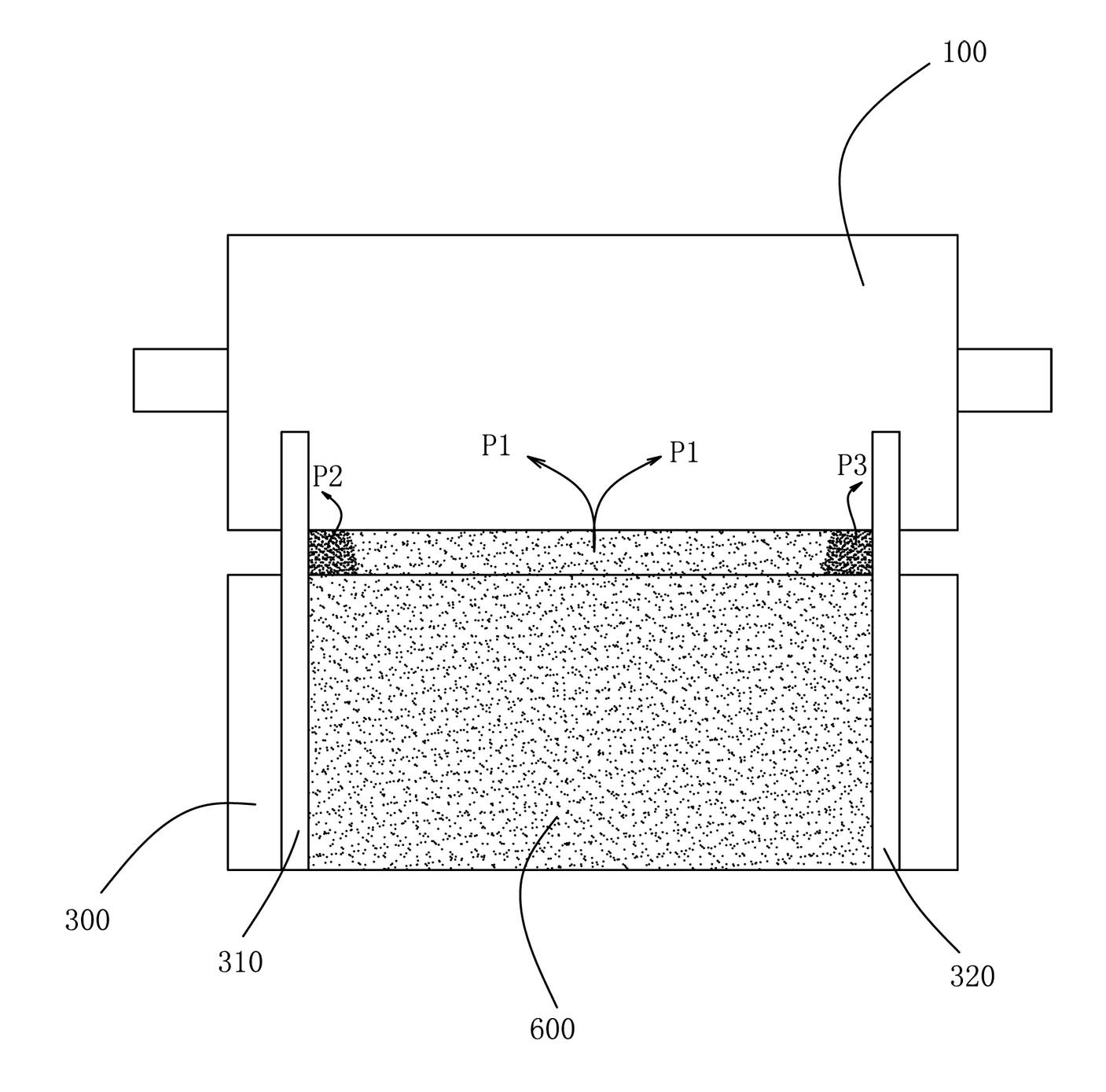
The second is that the head of the traditional gap coating machine uses the hopper 300 directly in contact with the driving roller 100, and the slurry is attached to the driving roller 100 through the rotation of the driving roller 100. In order to realize the adjustable width of the pole piece, Often can be set up two block pieces 310,320 in hopper 300, as figure 2 As shown, when the driving roller 100 rotates, the material pressure P1 in the middle of the driving roller 100 can be dispersed to both sides of the driving roller 100, while the material pressures P2 and P3 on the inner side of the driving roller 100 and the retaining pieces 310, 320 are only It can disperse outward in one direction, so that the slurry concentration of the slurry 600 in the middle part of the driving roller 100 and the two inner parts of the blocking pieces 310 and 320 is not equal, and the concentration of the two sides is greater than that of the slurry in the middle part of the driving roller 100 Concentration, the result of the final coating is that the slurry on both sides of the pole piece is thicker; secondly, the slurry is easy to settle in this direct hopper feeding method (because the existing slurry is an
aqueous solution of
solid powder) , and the mixing method of this hopper is to stir back and forth in the hopper 300 with a stirring rod, and the effect is extremely unsatisfactory; moreover, the dry material brought back from the driving roller 100 and not adhered to the back roller is re-entered The hopper 300 cannot be stirred evenly in time, which also affects the concentration of the slurry, thereby affecting the quality of the pole piece
[0004] In order to solve the problems of inaccurate and uneven material thickness, thick beginning, long trailing
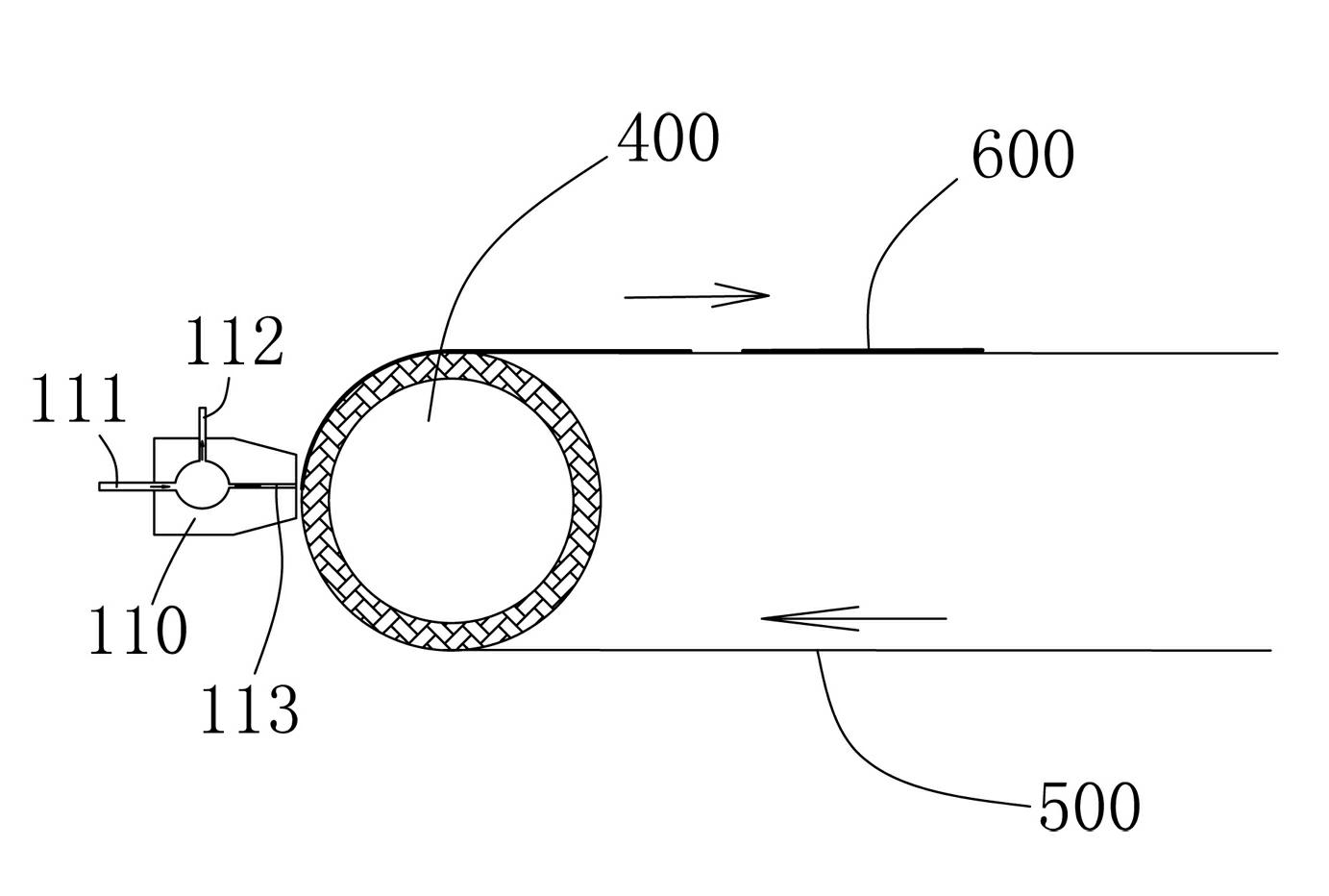
tail, thick side material on both sides of the pole piece, and unsatisfactory mixing in the hopper and other storage problems in the traditional gap coating machine head, people Invented an
extrusion coating machine head, such as image 3 As shown, it is directly provided with an extruding
nozzle 110 on one side of the back roller 400, and the extruding
nozzle 110 includes a slurry inlet 111, a slurry circulation outlet 112 and a slurry
nozzle 113, by controlling the slurry inlet 111 and The amount of feed and output of the slurry circulation outlet 112, so as to control the amount of material sprayed by the slurry nozzle 113
This kind of coating machine head can effectively overcome the inaccurate and uneven material thickness, thick beginning, long trailing tail, thick side material on both sides of the pole piece, and uneven mixing of the hopper in the gap coating machine head. The problem of ideal storage is too much, but the
extrusion coating machine has very high requirements on the slurry, and the particle size, concentration and dispersion of the slurry must be strictly controlled within the standard range, otherwise the slurry nozzle 113 will be blocked Therefore, the head of this
extrusion coating machine is generally equipped with a ten-stage dispersion mechanism, and its structure and control procedures are complicated. In this way, the price of the
extrusion coating machine head is very expensive, and domestic It is still unable to produce independently and completely depends on imports, which makes domestic related battery companies unaffordable

