Eureka AIR delivers breakthrough ideas for toughest innovation challenges, trusted by R&D personnel around the world.

Fixture for processing and detecting blade of aircraft engine

A technology of aero-engines and blades, which is applied in the direction of manufacturing tools, metal processing equipment, metal processing machinery parts, etc., can solve problems such as inability to perform online detection of blade processing accuracy and surface quality, large residual stress of blades, and increase production costs. Achieve the effects of light weight, improved pass rate, and improved production efficiency

Inactive Publication Date: 2012-02-22
SHANDONG UNIV
View PDF5 Cites 19 Cited by
  • Summary
  • Abstract
  • Description
  • Claims
  • Application Information

AI Technical Summary

Problems solved by technology

[0004] For the processing of blade-type thin-walled workpieces, it can be abstracted into the processing of slender shaft parts. At present, the commonly used fixture structure for processing is to use a chuck to clamp one end of the part, and the other end is to use a machine tool tailstock. The workpiece is clamped by the top-tightening method. According to the relevant knowledge of material mechanics, when the two ends of the slender shaft parts are clamped, the workpiece will be unstable, resulting in large deflection and excessive deformation of the workpiece. Causes a large residual stress inside the blade, resulting in waste of processed parts
[0005] The currently used aero-engine blade fixtures cannot perform online inspection of the machining accuracy and surface quality of the blade during processing. If there are unqualified conditions such as dimensional accuracy, shape accuracy, and position accuracy during processing, the machine tool will continue to complete the entire process. If the processing of the blade is not found to be substandard or waste until it is completely processed or applied, it will reduce production efficiency, increase production costs, and even cause catastrophic accidents

Method used


Image

  • Fixture for processing and detecting blade of aircraft engine
  • Fixture for processing and detecting blade of aircraft engine
  • Fixture for processing and detecting blade of aircraft engine

Examples


Embodiment Construction

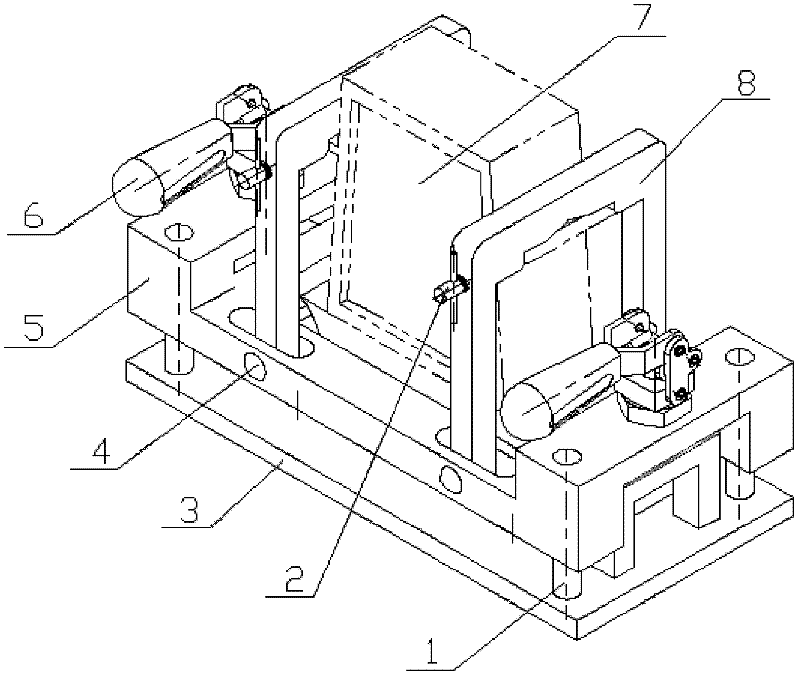
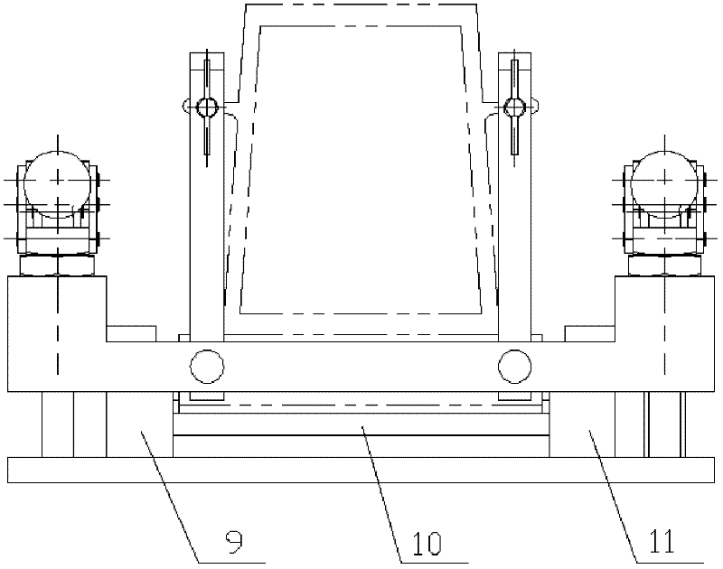
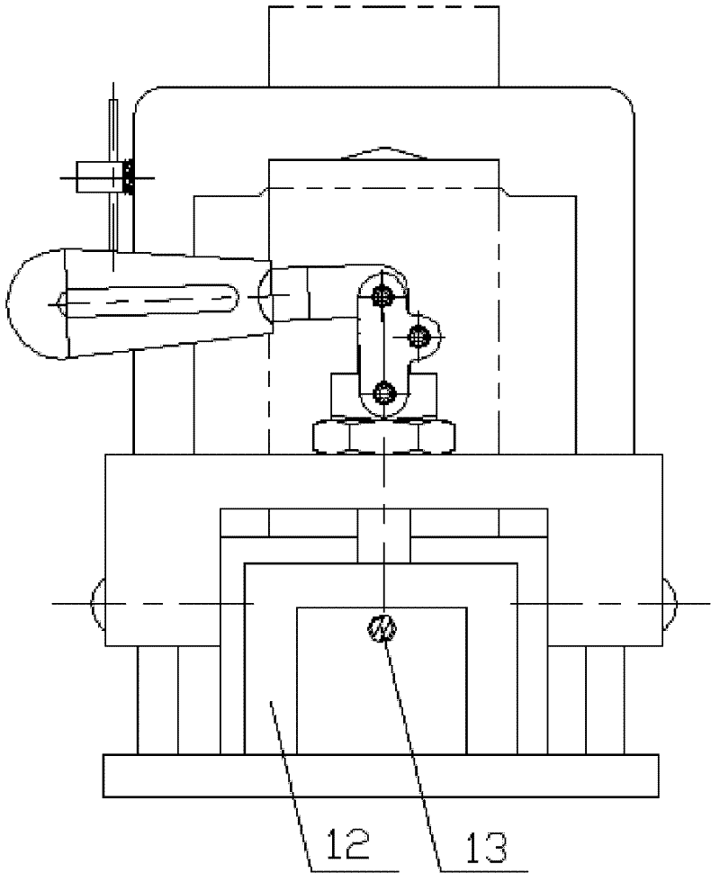
[0019] Such as figure 1 , figure 2 , image 3 and Figure 4 As shown, the fixture for machining and testing of aeroengine blades of the present invention includes a mounting base 3 , a clamping frame 5 , a rotating frame 8 and a clamping device 6 . The four corners of the installation base 3 are provided with guide posts 1, and the guide posts 1 and the installation base 3 can be connected by threads. The clamping frame 5 is installed on the installation base 3 through four guide columns 1 , the clamping frame 5 can move up and down along the guide columns 1 , and the guide columns 1 play a guiding role when the clamping frame 5 moves up and down. The clamping frame 5 is a frame structure with a hollow in the middle, so that the blade blank 7 can be placed on the positioning element on the installation base 3 through the hollow. The left and right sides of the clamping frame 5 are respectively provided with a set of clamping devices 6, and the clamping devices on the righ...


PUM


Abstract

The invention discloses a fixture for processing and detecting a blade of an aircraft engine. The fixture comprises a mounting base, a clamping framework, rotating frameworks and clamping devices, wherein a guide pillar is arranged on the mounting base; the clamping framework is mounted on the mounting base through the guide pillar; the clamping framework can move along the guide pillar; the clamping framework has a frame structure, in which a cavity is arranged; a set of clamping device is respectively arranged on each side of the clamping framework; two sets of clamping devices are both fixedly connected to the mounting base; two rotating frameworks are arranged between the two sets of clamping devices on the clamping framework; the two rotating frameworks are respectively mounted on the clamping framework through pin shafts; the rotating frameworks can swing round the pin shafts; spring plungers are arranged on the rotating frameworks; and a positioning element is mounted on the mounting base. The fixture provided by the invention can reduce a clamping stress generated during a process of clamping the blade, reduce clamping deformation of the blade and promote the processing precision of the blade. The fixture can simultaneously realized the process and on-line detection of the blade.

Description

technical field [0001] The invention relates to a fixture used for machining and on-line inspection of aeroengine blades, and belongs to the technical field of aeroengine blade machining. Background technique [0002] Aeroengine blades are one of the core components of the engine, and the performance of the engine depends to a large extent on the design and manufacturing level of the blade profile. The functional mission and working characteristics of the blade in the engine determine that the blade is the part of the engine with complex shape (three-dimensional space surface), large size span, severe stress condition, and the largest load. In order to meet the requirements of high performance, operating safety, reliability and long life of the engine, the blade must have precise dimensions, precise shape and strict surface integrity. However, the blades processed by the current numerical control processing method and processing equipment have a large stress deformation, an...

Claims


Application Information

Patent Timeline
Patent Type & Authority Applications(China)
IPC IPC(8): B23Q3/06
Inventor 刘战强王兵万熠刘继刚任小平艾兴
Owner SHANDONG UNIV
Why Eureka
Eureka Blog
Learn More