
Vibration reduction test device for vibration drilling

A testing device and drill technology, applied in measuring/indicating equipment, drilling/drilling equipment, components of boring machine/drilling machine, etc. Problems such as difficulty in guaranteeing hole processing quality, to achieve the effect of convenient and reliable data processing, improved hole processing quality and efficiency, and less workload

Inactive Publication Date: 2012-02-22
NANJING VOCATIONAL UNIV OF IND TECH
View PDF2 Cites 3 Cited by
  • Summary
  • Abstract
  • Description
  • Claims
  • Application Information

AI Technical Summary

Problems solved by technology

[0002] With the rapid development of the machinery industry, the requirements for the processing quality of mechanical parts are getting higher and higher. As far as mechanical parts are concerned, the processing of outer circles and planes is relatively easy to ensure the processing quality, while the processing of holes often has enlarged apertures and high precision. Quality problems such as reduction of surface roughness and increase in surface roughness make the processing quality of the hole not meet the requirements or reduce the processing efficiency, especially the quality of deep hole processing is more difficult to guarantee
One of the very important reasons is caused by the radial cutting chatter of hole machining. The radial cutting chatter problem of hole machining has always been the main obstacle to the machining quality and efficiency of the hole. In severe cases, it may even make the machining unable to continue. conduct

Method used


Image

  • Vibration reduction test device for vibration drilling
  • Vibration reduction test device for vibration drilling

Examples


Embodiment Construction

[0010] The drilling vibration reduction test device of the present invention will be described in detail below in conjunction with the accompanying drawings.

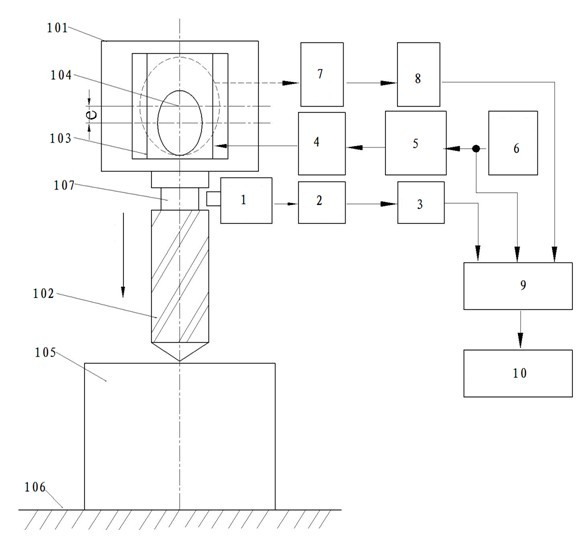
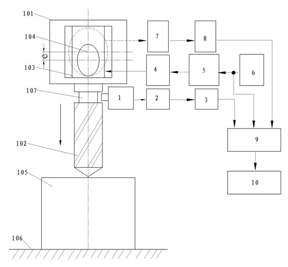
[0011] As shown in the figure, the drilling vibration reduction test device of the present invention is connected to the drilling machine 101, including an acceleration sensor 1, a charge amplifier 2, a level meter 3, a DC motor 4, a thyristor DC speed regulating device 5, and a speed command signal generator 6 , Velocimeter 7, Filter 8, Recorder 9 and Spectrum Analyzer 10. A workpiece 105 is mounted on a table 106 of a vertical drilling machine. The drill bit 102 is installed on the main shaft 103 of the drilling machine through the cam mechanism 104 and performs drilling processing on the workpiece 105 .

[0012] The output end of the speed command signal generator 6 is connected to the input end of the thyristor DC speed regulating device 5 , the output end of the thyristor DC speed regulating device 5 is connected ...


PUM


Abstract

The invention discloses a vibration reduction test device for vibration drilling. The device is connected with a drilling machine; a spindle of the drilling machine is connected with a drill bit; the device comprises an acceleration sensor, a charge amplifier, a level meter, a DC (direct current) motor, a silicon controlled DC speed regulation device, a rotation speed command signal generator, a speed meter, a filter, a recorder and a spectrum analyzer, wherein the rotation speed command signal generator is sequentially connected with the controlled silicon DC speed regulation device, the DC motor and the spindle of the machine tool; an input end of the acceleration sensor is connected with the neck of the drill bit; an output end of the acceleration sensor is connected with an input end of the charge amplifier; an output end of the charge amplifier is connected with an input end of the level meter; the speed meter is connected with the spindle of the machine tool and the filter respectively; an output end of the rotation speed command signal generator, an output end of the level meter and an output end of the filter are all connected with an input end of the recorder; and an output end of the recorder is connected with an input end of the spectrum analyzer. Through the invention, optimal speed change parameters can be effectively screened out, thus the hole processing quality and efficiency are improved.

Description

technical field [0001] The invention relates to a vibrating drill vibration reduction test device, in particular to a vibration drill vibration reduction multi-parameter test device based on variable speed cutting technology. Background technique [0002] With the rapid development of the machinery industry, the requirements for the processing quality of mechanical parts are getting higher and higher. As far as mechanical parts are concerned, the processing of outer circles and planes is relatively easy to ensure the processing quality, while the processing of holes often has enlarged apertures and high precision. Quality problems such as reduction and increase in surface roughness make the processing quality of the hole not meet the requirements or the processing efficiency is reduced, especially the quality of deep hole processing is more difficult to guarantee. One of the very important reasons is caused by the radial cutting chatter of hole machining. The radial ...

Claims


Application Information

Patent Timeline
IPC IPC(8): B23Q17/12B23B47/00
Inventor 王道林王红军徐峰
Owner NANJING VOCATIONAL UNIV OF IND TECH
Learn More