Position sensor-free vector control device for built-in permanent magnetic synchronous motor
A permanent magnet synchronous motor, vector control technology, applied in vector control systems, motor generator control, control of electromechanical transmissions, etc., can solve problems such as system runaway, achieve good low-speed operation performance, strong robustness, and achieve magnetic field The effect of precise directional control
- Summary
- Abstract
- Description
- Claims
- Application Information
AI Technical Summary
Problems solved by technology
Method used
Image

Examples
specific Embodiment approach 1
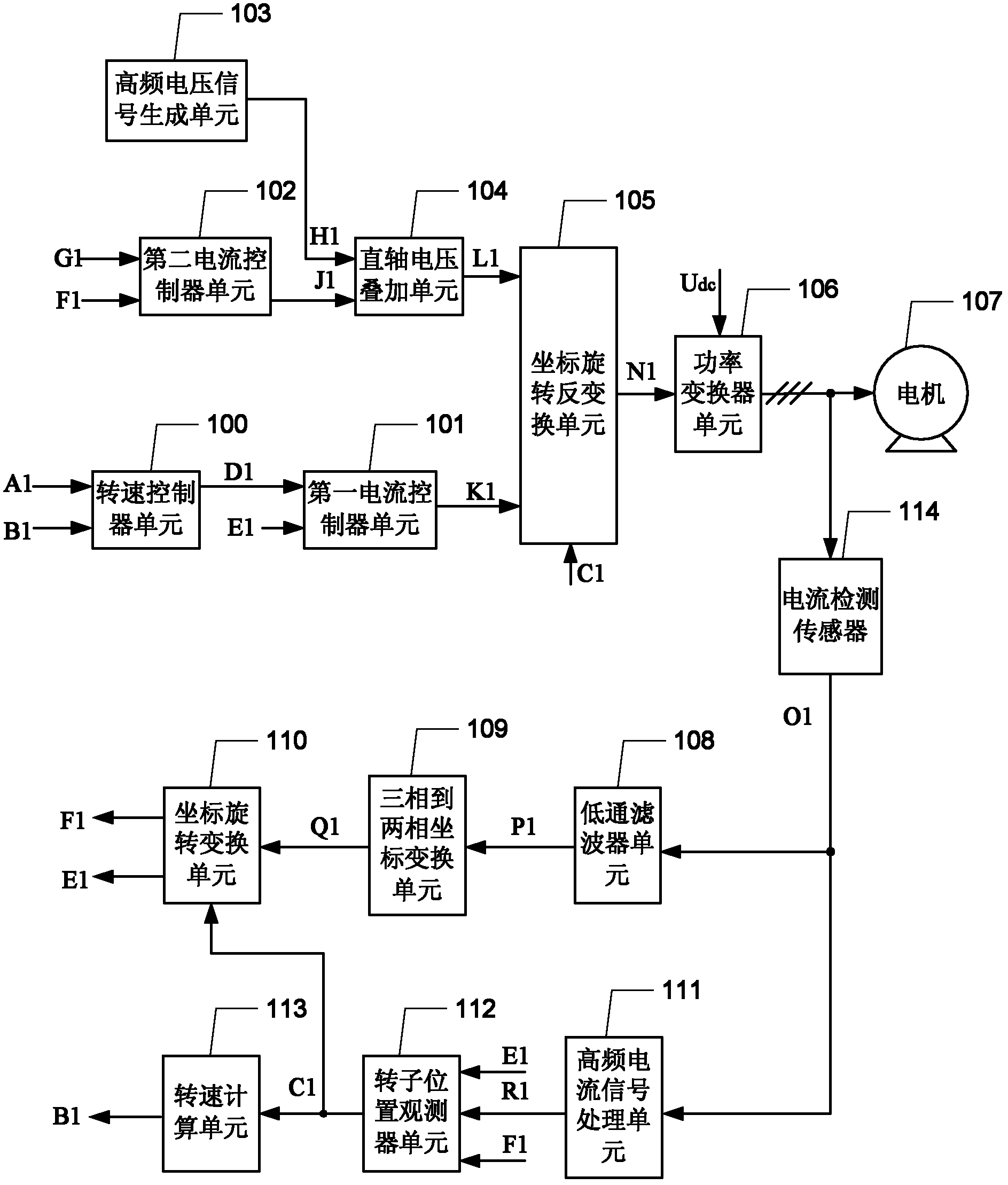
[0017] Specific implementation mode one: the following combination Figure 1 to Figure 4 Describe this embodiment mode, a built-in permanent magnet synchronous motor position sensorless vector control device described in this embodiment mode, it includes a speed controller unit 100, a first current controller unit 101, a second current controller unit 102, a high Frequency voltage signal generation unit 103, direct-axis voltage superposition unit 104, coordinate rotation inverse transformation unit 105, power converter unit 106, low-pass filter unit 108, three-phase to two-phase coordinate transformation unit 109, coordinate rotation transformation unit 110, High-frequency current signal processing unit 111, rotor position observer unit 112, speed calculation unit 113 and current detection sensor 114,
[0018] After the speed given command signal A1 and the estimated speed value B1 pass through the speed controller unit 100, the quadrature-axis torque current given value D1 is...
specific Embodiment approach 2
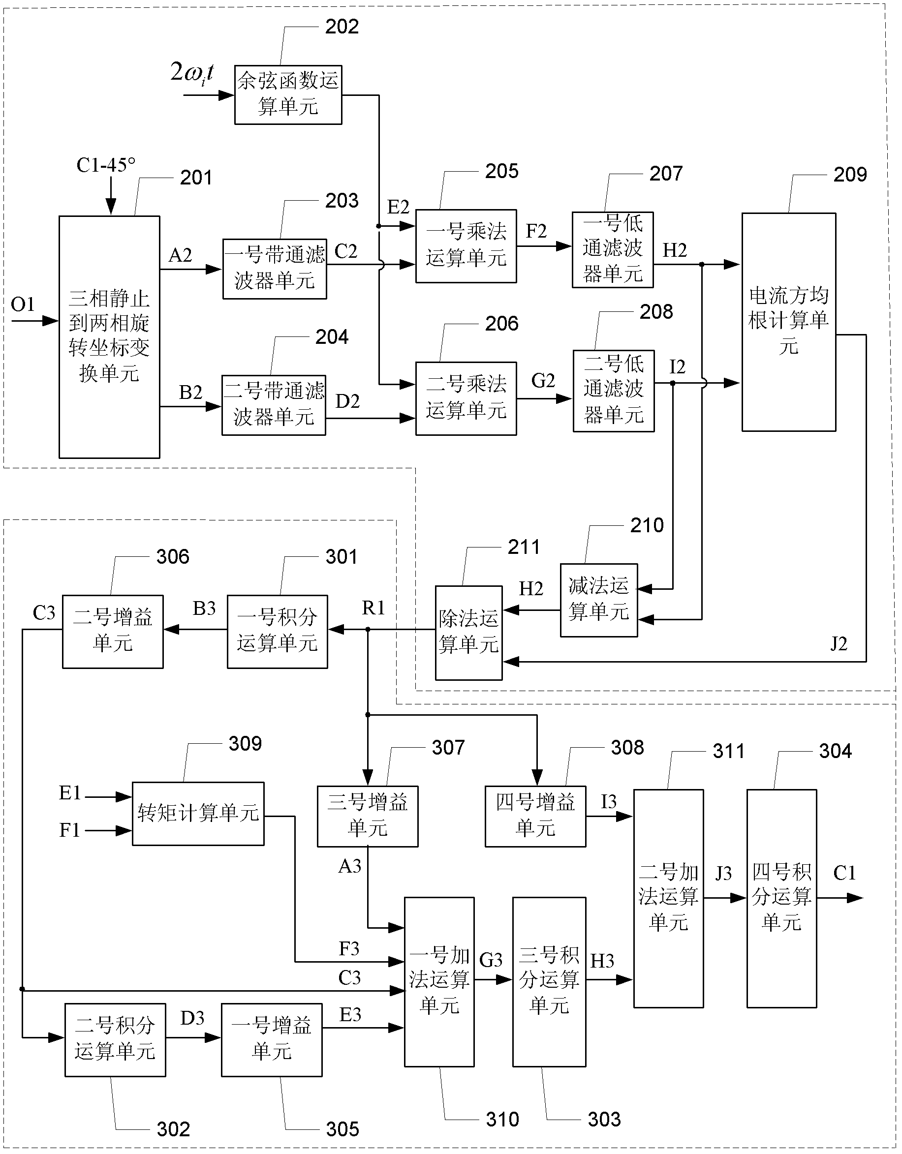
[0036] Specific Embodiment 2: This embodiment further describes Embodiment 1. The high-frequency current signal processing unit 111 includes a three-phase stationary to two-phase rotating coordinate transformation unit 201, a cosine function calculation unit 202, a No. 1 band-pass filter unit 203, No. 2 band-pass filter unit 204, No. 1 multiplication unit 205, No. 2 multiplication unit 206, No. 1 low-pass filter unit 207, No. 2 low-pass filter unit 208, current root-mean-square calculation unit 209, subtraction unit 210 and division operation unit 211,
[0037] The stator current sampling signal O1 is adjusted by the three-phase stationary to two-phase rotating coordinate transformation unit 201 to output the quadrature-axis current component A2 and the direct-axis current component B2. The value of the transformation angle C1 is 45°, twice the high-frequency voltage electrical angle After passing through the cosine function operation unit 202, the high-frequency signal E2 is ...
specific Embodiment approach 3
[0046] Embodiment 3: This embodiment further describes Embodiment 1. The rotor position observer unit 112 includes a No. 1 integral computing unit 301, a No. 2 integral computing unit 302, a No. 3 integral computing unit 303, a No. 4 integral computing unit 304, No. 1 gain unit 305, No. 2 gain unit 306, No. 3 gain unit 307, No. 4 gain unit 308, torque calculation unit 309, No. 1 addition unit 310, No. 2 addition unit 311,
[0047] The rotor position error signal R1 also passes through the No. 3 gain unit 307 to obtain the No. 3 gain signal A3, and the rotor position error signal R1 also passes through the No. 4 gain unit 308 to obtain the No. 4 gain signal I3.
[0048] The rotor position error signal R1 passes through the No. 1 integral operation unit 301 to obtain the No. 1 integral signal B3, and the No. 1 integral signal B3 passes through the No. 2 gain unit 306 to obtain the No. 2 gain signal C3, and the No. 2 gain signal C3 passes through the No. 2 integral operation unit ...
PUM
 Abstract
Description
Claims
Application Information
 - Generate Ideas
- Intellectual Property
- Life Sciences
- Materials
- Tech Scout
- Unparalleled Data Quality
- Higher Quality Content
- 60% Fewer Hallucinations
Browse by: Latest US Patents, China's latest patents, Technical Efficacy Thesaurus, Application Domain, Technology Topic, Popular Technical Reports.
© 2025 PatSnap. All rights reserved.Legal|Privacy policy|Modern Slavery Act Transparency Statement|Sitemap|About US| Contact US: help@patsnap.com