Induction motor control device and induction motor group control system

一种感应电动机、控制装置的技术,应用在交流电动机控制、四象限中的电动机控制、控制系统等方向,能够解决不普遍、切换损失增加等问题

Inactive Publication Date: 2012-02-22
岛田隆一
View PDF10 Cites 11 Cited by
  • Summary
  • Abstract
  • Description
  • Claims
  • Application Information

AI Technical Summary

Problems solved by technology

Therefore, there is an issue of increased switching loss in SVG
Therefore, it is not common to use these conventional reactive power compensating devices for reactive power compensation near the end of the power distribution system

Method used


Image

  • Induction motor control device and induction motor group control system
  • Induction motor control device and induction motor group control system
  • Induction motor control device and induction motor group control system

Examples


Embodiment Construction

[0038] Preferred embodiments of the present invention will be described in detail below with reference to the drawings. In addition, in this specification and drawings, the same code|symbol is attached|subjected to the structural element which has substantially the same function and structure, and repeated description is abbreviate|omitted.

[0039]

[0040] (1-1. Overall structure)

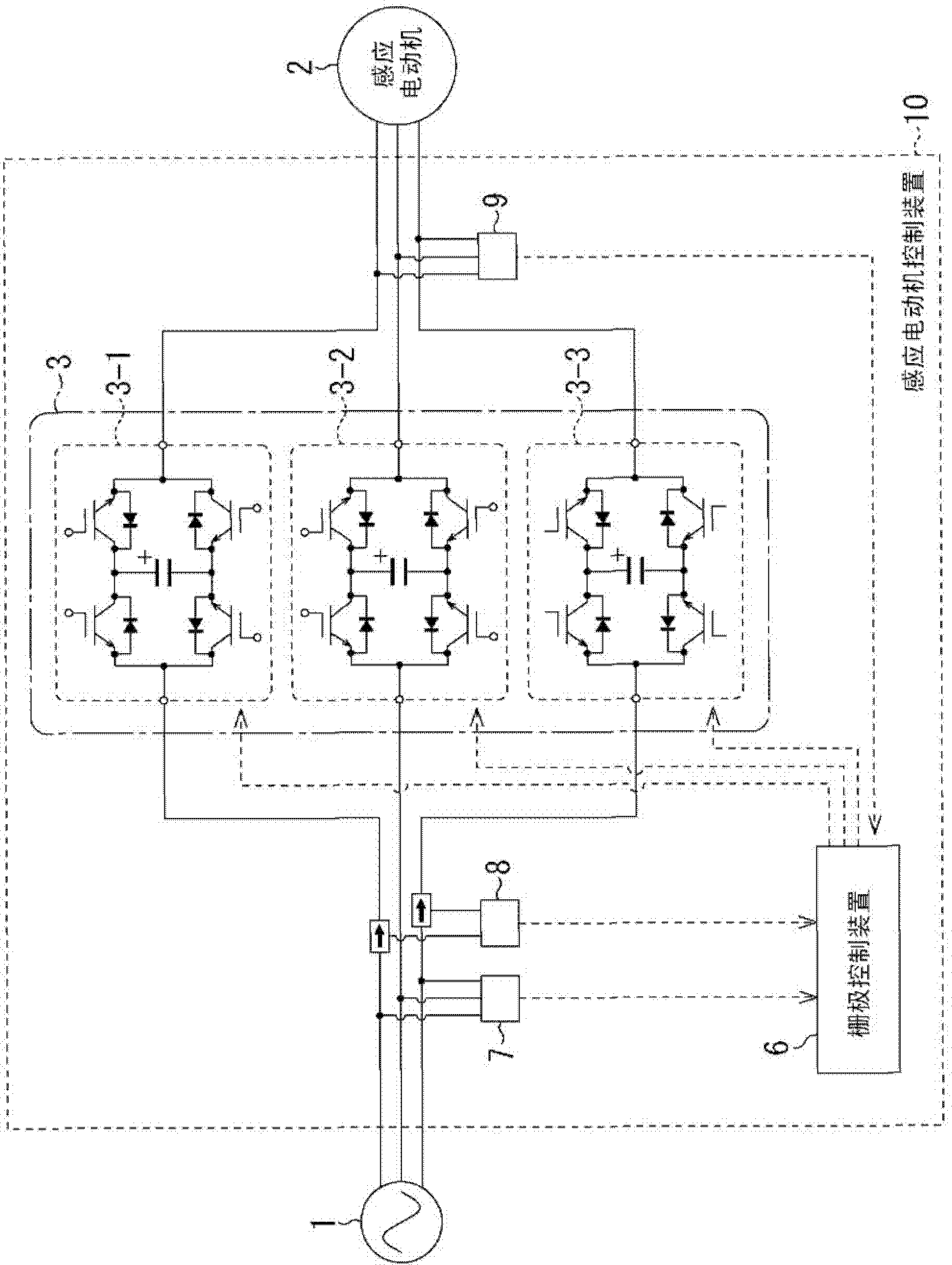
[0041] figure 1 An outline of an example of the configuration of the induction motor control device according to the first embodiment of the present invention is shown.

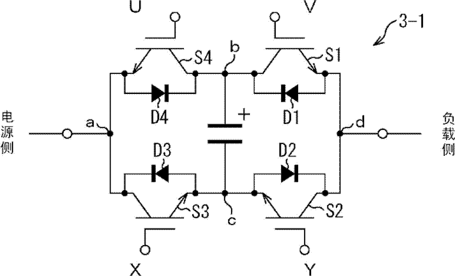
[0042] The induction motor control device 10 is configured to include the following parts: three magnetic energy regeneration switches 3 (magnetic energy regeneration switches 3-1 to 3-3), a grid control device 6, a voltage detection device 7, a current detection device 8, and a voltage detection device 9 .

[0043] The magnetic energy regeneration switch 3 is called MERS (Magnetic Energy Recovery Switch). In this embodime...


PUM


Abstract

In an induction motor group control system, magnetic energy recovery switches (3) are connected in series to an induction motor (2) directly driven by a commercial power supply, and a plurality of induction motor control devices (10) enabling voltage control and reactive power control of the induction motor (2) are employed to control generation of reactive power so as to maximize a power factor of the entire plurality of AC loads including the induction motor or compensate variations in voltage of an AC power supply (1).

Description

technical field [0001] The present invention relates to an induction motor control device and an induction motor unit control system, and particularly relates to a technology suitable for reducing reactive power and stabilizing voltage in a power system having a load including an induction motor. Background technique [0002] Among electric motors, induction motors are relatively easy to drive from startup to operation, and can be used only by being directly connected to a commercial power supply, so they are widely used in various applications. [0003] With the development of energy electronics in recent years, it is possible to drive an induction motor at a variable speed. That is, the induction motor is driven by an inverter that first converts AC power into DC power, and then reversely converts the DC power into AC with different frequencies by switching semiconductor switches at a high frequency. electricity. However, fan motors, compressors, pump motors, and the lik...

Claims


Application Information

Patent Timeline
Patent Type & Authority Applications(China)
IPC IPC(8): H02P27/06H02J3/18H02P5/74
CPCH02J3/1892H02M1/4216H02M5/293H02P5/74H02P27/16H02P23/07H02P23/26Y02B70/10H02M1/008
Inventor 福谷和彦成泽英夫岛田隆一矶部高范北原忠幸
Owner 岛田隆一
Why Eureka
Try Eureka