Crusher

A crusher and driving machine technology, applied in the field of machinery, can solve the problems of untimely maintenance, low design life of the coupling, high cost, etc., and achieve the effects of convenient installation and replacement, long service life and high degree of safety

Active Publication Date: 2012-02-29
西安海泰科技有限公司
View PDF9 Cites 8 Cited by
  • Summary
  • Abstract
  • Description
  • Claims
  • Application Information

AI Technical Summary

Problems solved by technology

Its casting molding is difficult, has strict requirements on equipment, high cost, and time-consuming and labor-intensive processing.
[0005] 3. At present, the gear box of the grading crusher is connected with the toothed roller shaft of the crusher by a gear coupling. Particles such as dust in the crushing field are easy to enter the connection pair between the gear coupling and the shaft from the output shaft of the gear box, and the lubrication The agent is mixed together, resulting in the life of the coupling being lower than the design life, increasing the maintenance cost of the equipment
[0006] 4. The current control systems of grading crushers and roller crushers are relatively simple, and there is no system for predicting the trend of crusher failures and diagnosing failures
However, in actual production, there have been situations such as crusher bearing damage, spindle fracture, and gearbox damage.
Analyzing the reasons, the above situation is mainly caused by the increased impact of the crusher when it is working, and the untimely maintenance
At present, there is no effective monitoring and fault diagnosis system to ensure the safety of the crusher.

Method used


Image

  • Crusher
  • Crusher
  • Crusher

Examples


Embodiment Construction

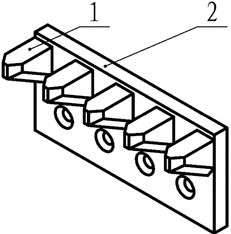
[0036] see figure 1 The side comb structure of the crusher used in the present invention includes a plate 1 and teeth 2 arranged on the plate 1. The teeth 2 are welded or clamped on the plate 1, preferably welded on the plate 1. The number of teeth 2 can be one or more, if more than one, multiple teeth 2 are welded on the same side of the plate 1 in parallel. Both the plate 1 and the teeth 2 are made of wear-resistant steel plates.

[0037] During the specific processing of the side comb structure, the side comb structure of the crusher is formed by welding plate 1 and tooth 2, and the wear-resistant steel plate is cut into plate 1 and tooth 2 by flame cutting, water cutting and other cutting methods. 2 shape, use the edge milling machine to carry out edge treatment and chamfering on the cut plate, if the blanking method adopted can meet the appearance requirements, then no edge treatment is required. After the blanking and edge processing are completed, the welding surface ...


PUM


Abstract

The invention discloses a crusher, which comprises a crusher drive and transmission device, wherein the crusher drive and transmission device comprises a driver, a first flat key, a second flat key, a hydraulic coupler, a hydraulic coupler protective cover, a first spline, a gear coupling and a gearbox, wherein the driver is connected with the hydraulic coupler through the first flat key; the hydraulic coupler is connected with the gearbox through a second flat key; the hydraulic coupler protective cover covers the hydraulic coupler and is connected with the gearbox and the driver respectively; the gear coupling is connected with the gearbox through the first spline; the gearbox is connected with a gearbox suspending bracket; and the gearbox comprises a cover plate on the top, a baffle plate on the bottom, a first oil release hole formed on the side wall of the gearbox, and a second oil release hole formed on the side wall of the gearbox of the crusher. The crusher is hardly deformed, high in safety and low in cost, spare parts of the gearbox are reduced, the using state of the crusher can be monitored in real time, and special casting equipment is not needed.

Description

technical field [0001] The invention belongs to the field of machinery and relates to a crusher. Background technique [0002] The various crushers commonly used at present have the following disadvantages: [0003] 1. Double-roll crushers and grading crushers commonly used in coal and mines are driven by each toothed roller independently, while the toothed rollers of crushers generally appear in pairs. Therefore, a pair of toothed rollers needs to be equipped with two types of symmetrical gearboxes. One each, which increases the related research and development costs and the types and costs of spare parts in stock for the complete crusher enterprise. The gear box with the same structure is used on the counter-toothed rollers, which can not only reduce the research and development cost, but also reduce the number of gear box spare parts for the end user, saving money and warehouse space. At the same time, because the crusher uses a common base to install the drive and tran...

Claims


Application Information

Patent Timeline
Patent Type & Authority Applications(China)
IPC IPC(8): B02C4/42B02C4/40B02C4/28B02C25/00B02C4/02
Inventor 杨楚郝君赵宽明侯兴军李江文樊荣王磊朱允进
Owner 西安海泰科技有限公司
Why Eureka
Try Eureka