Compressor oil pump system

A compressor pump and oil system technology, which is applied to pump components, mechanical equipment, variable capacity pump components, etc., can solve the problem of small passage area, affecting the movement range lubrication, poor oiling speed and poor pumping ability of pump oil, etc. problem, to achieve the effect of ensuring gas passage and bending resistance

Active Publication Date: 2014-10-08
黄石东贝压缩机有限公司
View PDF5 Cites 0 Cited by
  • Summary
  • Abstract
  • Description
  • Claims
  • Application Information

AI Technical Summary

Problems solved by technology

However, according to the design principle, the distance between the end face of the shaft hole of the cylinder block 1 and the end face of the counterbore of the rotor 3 at the air hole 8b is only 0.2-0.53 mm. Since the gas channel does not extend upward, the upper part of the crankshaft is solid, and its bending resistance has been improved. Reinforced, but equivalent to the gas channel is only 0.2 ~ 0.53mm, the channel area is extremely small, not very smooth, the oiling speed and pumping capacity of the pump oil are not very good
Therefore, the advantage of this method is that the crankshaft has a good shaft bending ability, but the disadvantage is that the gas passage is not smooth, which leads to poor oiling speed and pumping ability of the pump oil, which affects the lubrication of the moving range.

Method used


Image

  • Compressor oil pump system
  • Compressor oil pump system
  • Compressor oil pump system

Examples


Embodiment 1

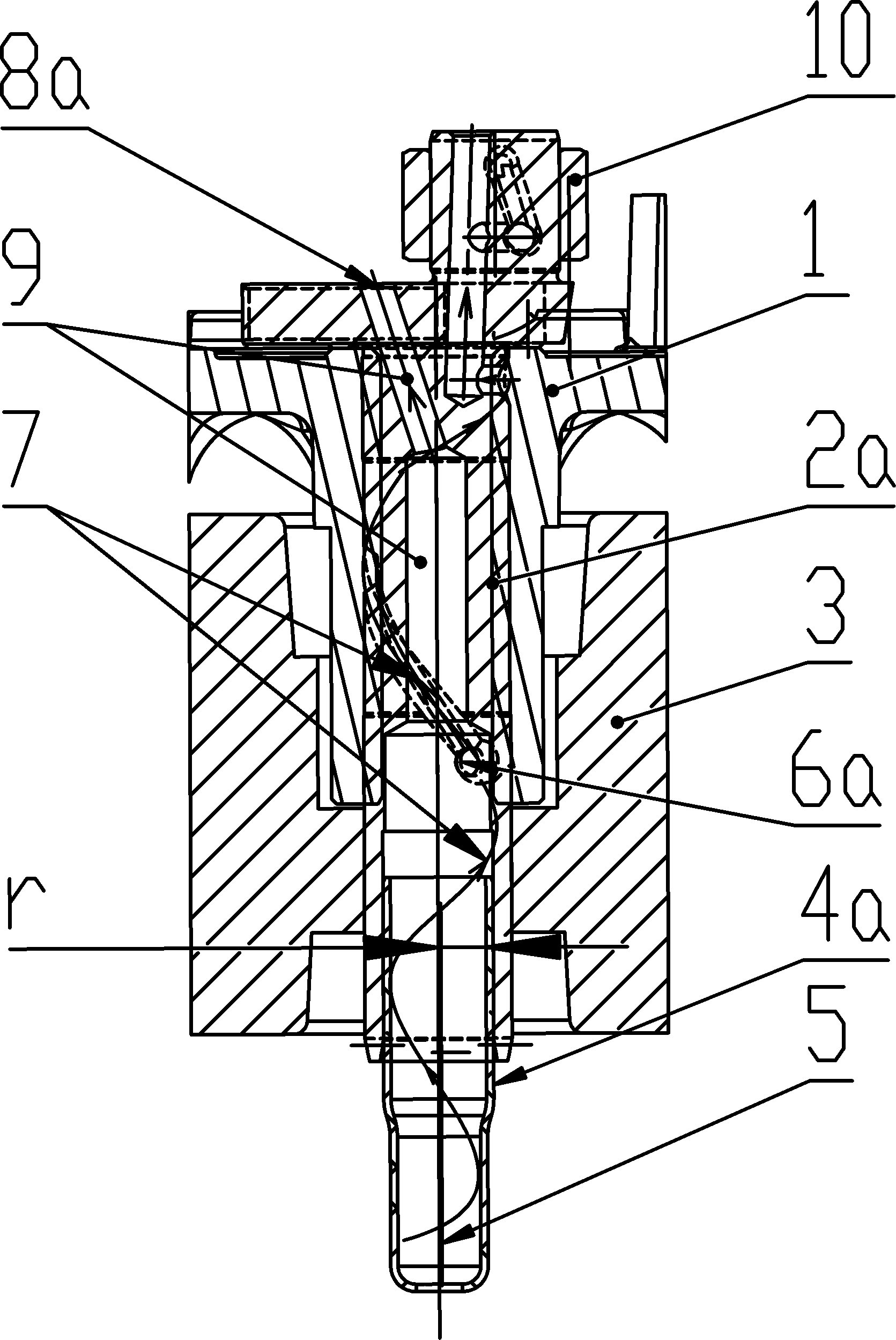
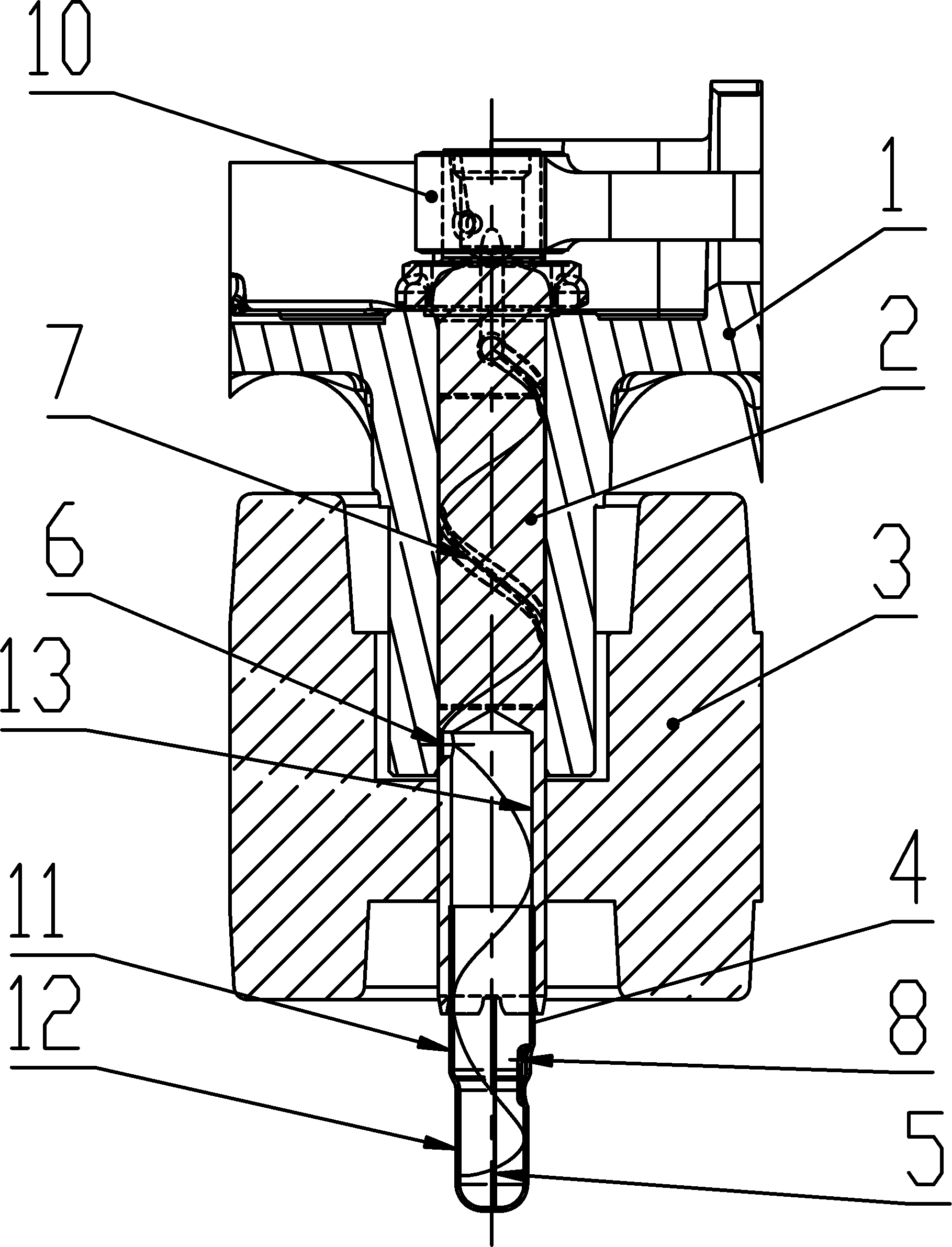
[0029] Such as image 3 , 6 , 7, the present embodiment is a compressor oil pump system with a reciprocating piston crankshaft-connecting rod mechanism, mainly including a crankshaft 2 and an oil suction pipe 4 built in the cylinder block 1 and rotor 3; the upper end of the crankshaft 2 is a solid The rod body part and the lower end are hollow oil guide pipes 13, and one (or multiple) helically extended oil grooves 7 are arranged on the outer surface of the solid rod body part. It communicates with the oil guide pipe, and the upper end of the oil groove 7 communicates with the crankshaft 2 top.

[0030] As a preferred solution, the oil-absorbing spacer 5 is embedded in the oil-suction pipe 4a with an interference fit, and there is a gap between the oil-suction spacer 5 and the air holes 8, so as not to block the passage of airflow.

[0031] The oil suction pipe 4 is a cylindrical tube with an inner hollow and open upper and lower ends, and is divided into an upper large-diam...

Embodiment 2

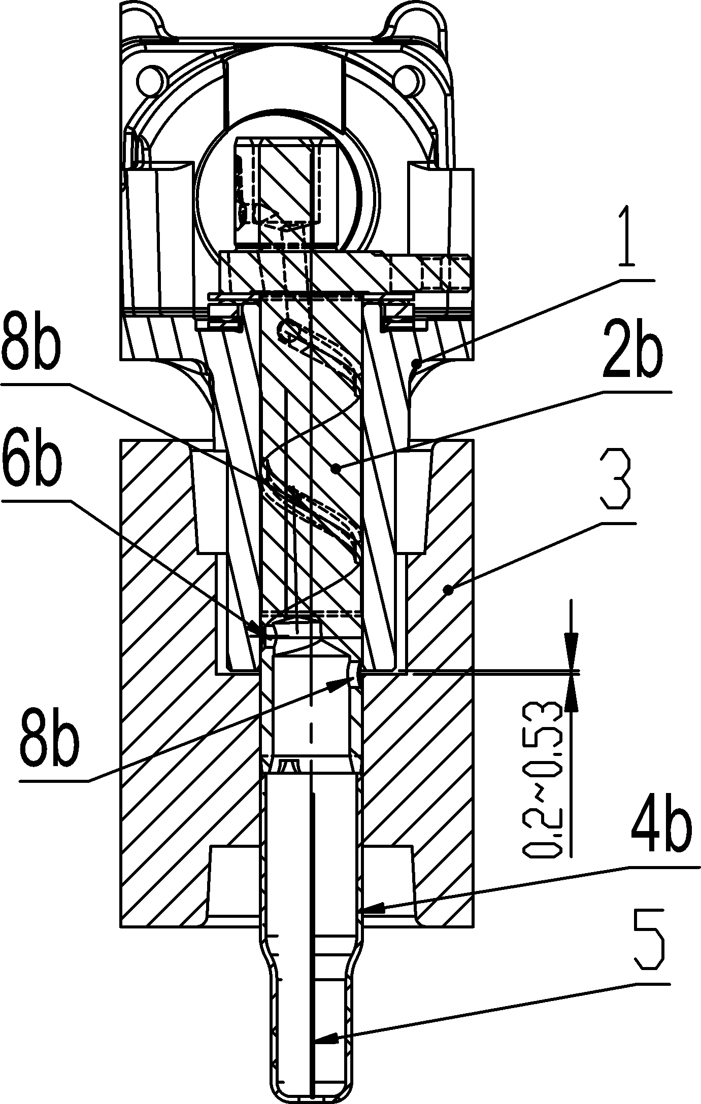
[0036] See attached Figure 4 , 6, 7. The main structure of the technical solution of embodiment two is basically the same as embodiment one; the difference is: the oil guide pipe 13 of the crankshaft 2 is in interference fit with the inner hole of the rotor 3; Hole interference fit; the oil guide pipe 13 and the large-diameter end 11 are butted in the inner hole of the rotor 3 to form an oil passage, such as Figure 4 shown.

[0037] The air hole 8 is still located below the lower end surface of the rotor 3 and above the oil surface during assembly, thereby ensuring that the air flow inside the oil pump system communicates with the external air pressure, thereby ensuring that the oil rises smoothly.

[0038] When working, the small-diameter end 12 of the lower part of the oil suction pipe 4 is partially submerged in the oil. When the crankshaft 2 and the oil suction pipe 4 rotate under the drive of the motor rotor 3, the centrifugal force pushes the oil to spiral on the inn...

Embodiment 3

[0040] See attached Figure 5-7 The main structure of the technical solution of embodiment three is basically the same as that of embodiments one and two; the difference is that the large-diameter end 11 of the oil suction pipe 4 is sleeved on the outside of the lower end of the oil guide pipe 13 connected to the crankshaft 2, and at the joint Above, the oil guide pipe 13 of the crankshaft 2 has an interference fit with the inner hole of the rotor 3; the oil guide pipe 13 and the large-diameter end 11 are connected to each other to form an oil passage, such as Figure 5 shown.

[0041] The air hole 8 is still located below the lower end surface of the rotor 3 and above the oil surface during assembly, thereby ensuring that the air flow inside the oil pump system communicates with the external air pressure, thereby ensuring that the oil rises smoothly.

[0042] When working, the small-diameter end 12 of the lower part of the oil suction pipe 4 is partially submerged in the oil...


PUM


Abstract

The invention relates to an oil pumping system of a compressor. The oil pumping system mainly comprises a crankshaft arranged in a cylinder seat and a rotor, and an oil suction pipe connected with the lower end of the crankshaft, wherein the upper end of the crankshaft is a solid rod body and the lower end of the crankshaft is a hollow oil guide pipe; a spirally extending oil groove is formed on the outer surface of the solid rod body; an oil hole by which the oil groove is communicated with the oil guide pipe is formed at the lower end, connected with the oil guide pipe, of the oil groove; the oil suction pipe is a cylindrical pipe with a hollow inner part, and openings are formed at the upper end and the lower end of the cylindrical pipe; at least one air hole is formed in the oil suction pipe; the surface or the curved surface where the air hole is formed is inwards contracted relative to the cylindrical surface of the oil suction pipe; and during assembly, the air hole is positioned below the lower end face of the rotor and above the oil level. By the structure, the problem of unsmoothness, caused by a small gap between the end face of an axial hole of the cylinder seat and a counter bore of the rotor, of an air channel can be solved completely; furthermore, as the air channel does not extend towards the upper end of the crankshaft and the upper end of the crankshaft is the solid rod body, the anti-bending capacity of the crankshaft when the diameter of the crankshaft is reduced and the smoothness of the air channel can be guaranteed.

Description

technical field [0001] The invention belongs to the field of compressor manufacturing, and in particular relates to an oil pumping system for a refrigeration compressor. Background technique [0002] Hermetic refrigeration compressors generally use a reciprocating piston crankshaft-connecting rod mechanism, such as figure 1 As shown, it includes a cylinder block 1, a crankshaft 2a, and a connecting rod 10. The crankshaft 2a rotates to push the connecting rod 10 and the piston (not shown) to reciprocate. Its oil pumping system is composed of crankshaft 2a, oil suction pipe 4a, and oil suction spacer 5. Oil suction spacer 5 is embedded in the interference phase of oil suction pipe 4a. Oil suction pipe 4a is in interference fit with crankshaft 2a at the lower end of crankshaft. in oil. The oil pumping principle is as follows. When the rotor 3 is driven by the motor (not shown in the figure) to rotate with the crankshaft 2a and the oil suction pipe 4a, the oil will flow along ...

Claims


Application Information

Patent Timeline
Patent Type & Authority Patents(China)
IPC IPC(8): F04B39/02
Inventor 方泽云何仁庶黄强胜孙继勇胡倩云
Owner 黄石东贝压缩机有限公司
Why Eureka
Try Eureka