
Method for testing bending fatigue reliability of low dimensional conducting material
A conductive material and bending fatigue technology, which is applied in the field of testing system for bending fatigue reliability, can solve problems such as fatigue, inability to accurately measure crack initiation life, and large error in fatigue life measurement of conductive thin film materials, so as to achieve accurate and accurate measurement The effect of sample resistance value and its change, fatigue test range
- Summary
- Abstract
- Description
- Claims
- Application Information
AI Technical Summary
Problems solved by technology
Method used
Image

Examples
Embodiment 1
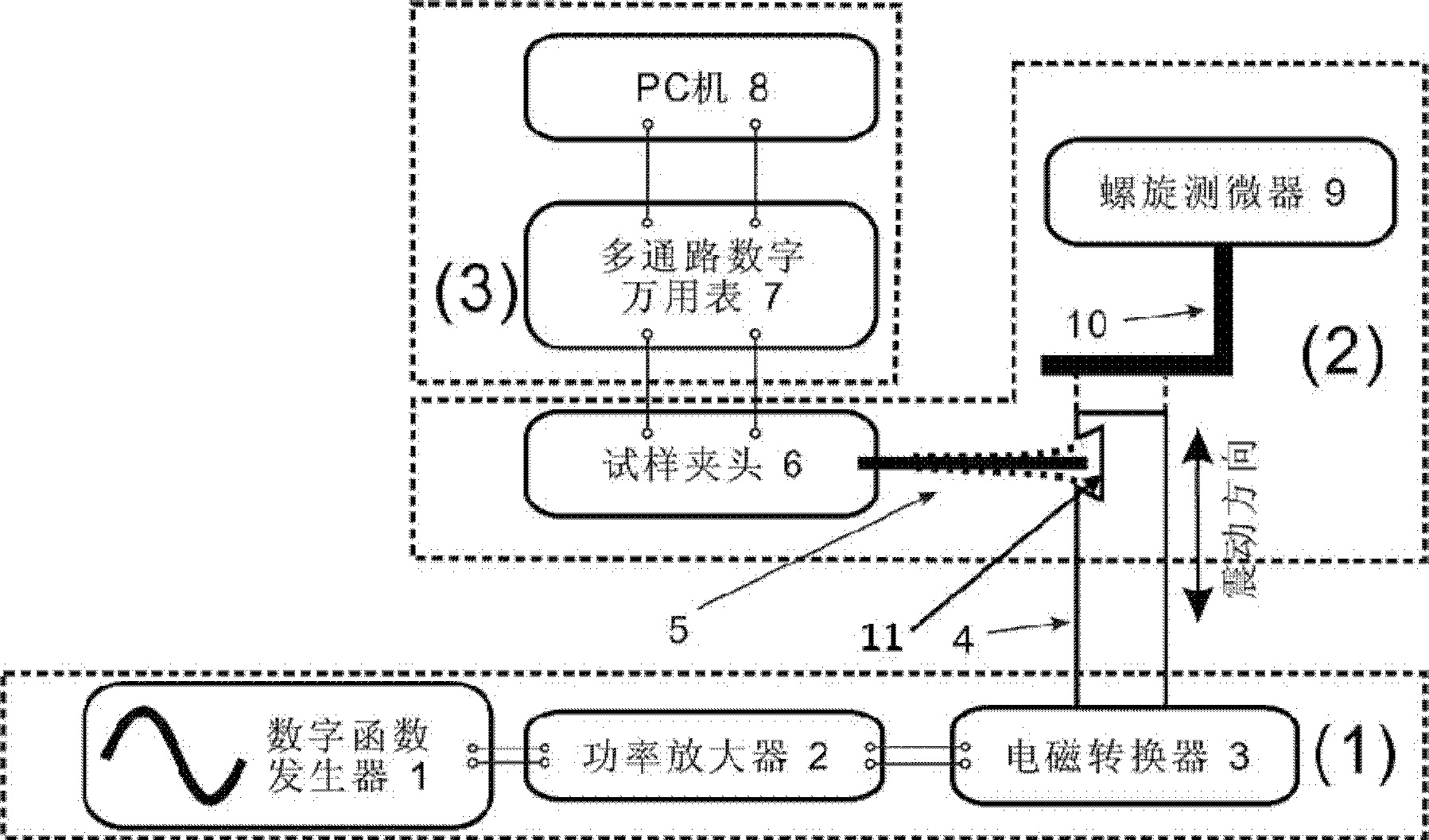
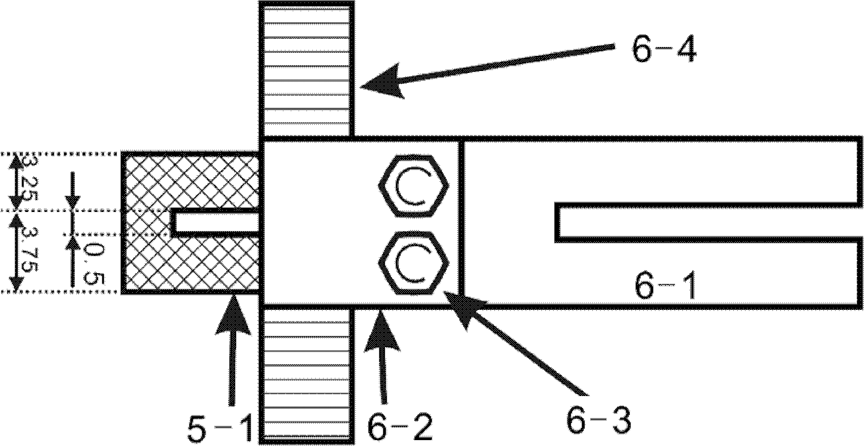
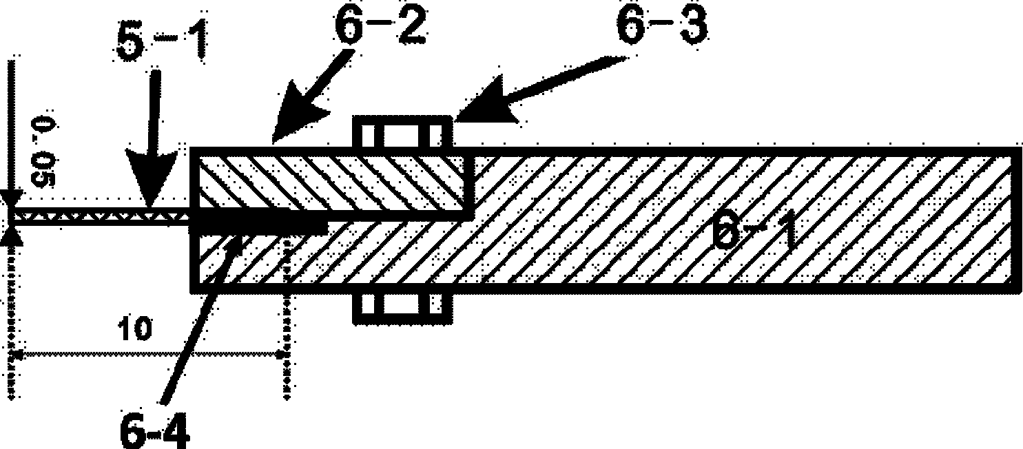
[0063]The metal nickel foil with a thickness of 50 μm is mechanically polished and electrolytically polished, and the thickness of the tested conductive sample 5 is 34 μm, which is cut into a U-shaped small-scale tested conductive sample 5-1, and the sample is fixed on the On the sample fixture 6, the effective length of the cantilever beam is selected to be 3mm, and the assembly diagram of the sample and the sample fixture 6 device is shown in Figure 2. Before the fatigue test, the tensile stress-strain curve of the nickel foil was obtained by the uniaxial tensile test to obtain the constitutive relationship in the finite element simulation. Using the constitutive relationship, the maximum strain at the root of the sample was calculated to be 1.0921%. The sine wave with a frequency of 50 Hz is selected as the fatigue waveform of the load, the amplitude of the sample is 2 mm, and the tension and compression symmetrical fatigue loading is adopted. From the real-time resistance ...
Embodiment 2
[0065] Bend the drawn pure copper wire with a diameter of 25 μm into an arc, and fix its two ends on the fixture 6, select the length of the cantilever beam of the filament to be 3.5mm, and the assembly diagram is as follows Figure 4 shown. Before the fatigue test, the tensile stress-strain curve of the copper wire was obtained by the uniaxial tensile test to obtain the constitutive relationship in the finite element simulation. Using the constitutive relationship, the maximum strain at the root of the sample was calculated to be 8.5%. The sine wave with a frequency of 50 Hz is selected as the fatigue waveform of the load, the amplitude of the sample is 2 mm, and the tension and compression symmetrical fatigue loading is adopted. A multi-channel digital multimeter is used to collect the resistance value of the sample during the fatigue test. From the real-time resistance value of the sample measured during the fatigue test, the relative change rate of the sample resistance i...
PUM
| Property | Measurement | Unit |
|---|---|---|
| size | aaaaa | aaaaa |
| size | aaaaa | aaaaa |
| thickness | aaaaa | aaaaa |
Abstract
Description
Claims
Application Information