
Steel-wood combined bridge structure with pored steel plate connecting piece

A combination technology of perforated steel plate and steel-wood, which is applied to bridges, bridge parts, bridge construction, etc., can solve the problems of increasing the spanning capacity of wooden bridges, a large number of connecting components, and inconvenient construction, so as to improve driving comfort, The effect of simple structure and convenient construction

Inactive Publication Date: 2012-03-07
CHANGAN UNIV
View PDF8 Cites 8 Cited by
  • Summary
  • Abstract
  • Description
  • Claims
  • Application Information

AI Technical Summary

Problems solved by technology

[0004] The technical problem to be solved by the present invention is to provide a steel-wood composite bridge structure with perforated steel plate connectors in view of the above-mentioned deficiencies in the prior art. Good, while increasing the spanning capacity of wooden bridges, it can effectively solve the defects of existing steel-wood composite bridges, such as a large number of connecting components, inconvenient construction, and low construction efficiency.

Method used


Image

  • Steel-wood combined bridge structure with pored steel plate connecting piece
  • Steel-wood combined bridge structure with pored steel plate connecting piece
  • Steel-wood combined bridge structure with pored steel plate connecting piece

Examples


Embodiment 1

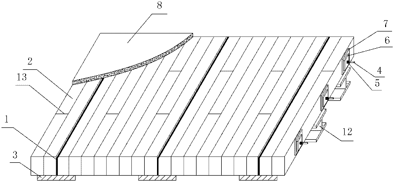
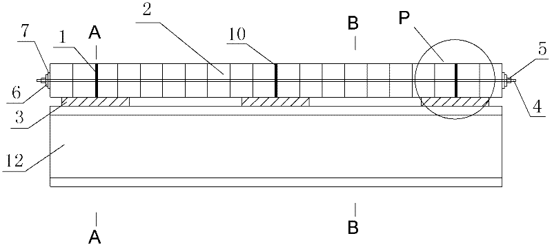
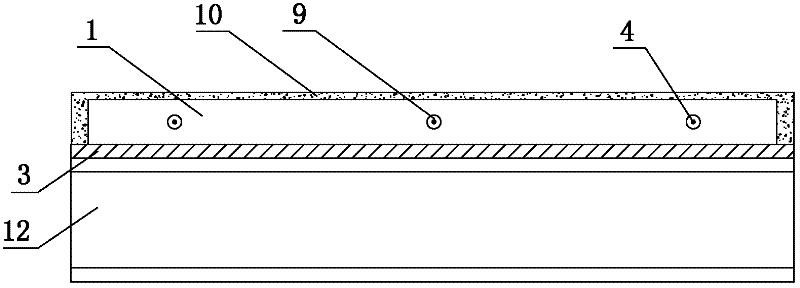
[0042] Such as figure 1 , figure 2 , image 3 , Figure 4 , Figure 5 and Figure 6As shown, the present invention includes a bridge superstructure and a bridge substructure that integrally supports the bridge superstructure, and the bridge superstructure includes a wooden bridge deck composed of a plurality of rectangular planks 2 laid on the same plane and positioned at The bottom load-bearing structure directly below the wooden bridge deck, in which a plurality of perforated steel plates 1 arranged longitudinally are sandwiched. The bottom load-bearing structure includes a plurality of lower beams arranged on the same plane and a plurality of lower beams 12 arranged on the same plane, the plurality of lower beams are arranged in parallel, and the plurality of lower beams 12 are arranged in parallel. They are arranged in parallel, and the lower longitudinal beams and the lower cross beams 12 are arranged perpendicularly. The plurality of lower cross beams 12 are fixed...

Embodiment 2

[0056] Such as Figure 7 , Figure 8 , Figure 9 , Figure 10 , Figure 11 and Figure 12 As shown, in this embodiment, the difference from Embodiment 1 is that: the lower longitudinal beam is a longitudinal I-beam 14, the lower cross beam 12 is an I-beam, and the plurality of lower longitudinal beams and the plurality of The lower beams 12 are arranged on the same plane. In actual construction, a plurality of the lower longitudinal beams may also be arranged directly under the lower cross beam 12 . In this embodiment, the plurality of lower longitudinal beams and the plurality of lower cross beams 12 are assembled into one body through a plurality of connecting bolts 15, and the perforated steel plate 1 is vertically welded on the upper wing of the longitudinal I-beam 14 Middle of top edge. On the premise of adding load-bearing beams of the bridge, the bridge superstructure formed in this embodiment can be directly applied to bridges with relatively large spans.

[00...


PUM


Abstract

The invention discloses a steel-wood combined bridge structure with a pored steel plate connecting piece. The steel-wood combined bridge structure comprises an upper bridge structure, a lower bridge structure, a wood bridge panel formed by splicing a plurality of rectangular wood plates, and a bottom bearing structure located right below the wood bridge panel, wherein a plurality of pored steel plates are sandwiched in the wood bridge panel; the bottom bearing structure comprises a plurality of lower longitudinal beams distributed on a same plane and a plurality of lower cross beams distributed on a same plane; the pored steel plates and the lower longitudinal beams are identical in number, and the plurality of pored steel plates are respectively fastened right above the plurality of longitudinal beams; and the plurality of rectangular wood plates and the plurality of pored steel plates are assembled into a whole through transversely distributed prestress steel bundles, and the plurality of pores steel plates and the prestress steel bundles jointly bear the shear force and the lift force among the steel-wood structure. The steel-wood combined bridge structure disclosed by the invention has the advantages of simple structure, convenience for construction, definite stress, reliability in connection and good use effect, and various defects of the traditional steel-wood combined bridge can be overcome while the spanning capability of the wood structure bridge is increased.

Description

technical field [0001] The invention belongs to the technical field of bridge construction engineering, and in particular relates to a steel-wood composite bridge structure provided with perforated steel plate connectors. Background technique [0002] The steel-wood composite structure bridge is a bridge structure that uses a combination of steel girders and wooden bridge decks. It has the advantages of light weight, fast construction speed, good durability, and high degree of industrialization. It is currently a bridge form that has attracted much attention in the bridge industry. one. The stress-laminated wooden bridge deck introduces prestressing technology into the wooden bridge deck to improve its integrity, and has higher bearing capacity and better performance than ordinary screw-laminated bridge decks. Therefore, the steel stress laminated wooden bridge deck combined bridge structure can give full play to the advantages of steel structure and wooden structure, high ...

Claims


Application Information

Patent Timeline
Patent Type & Authority Applications(China)
IPC IPC(8): E01D19/12
Inventor 刘永健傅梅珍宋瑶姚晓荣刘玉娟姚文奇李娜
Owner CHANGAN UNIV
Learn More