Tracking system of large-angle fast steering mirror

A tracking system and reflector technology, applied in the direction of control, installation, optics, etc. using feedback, can solve problems such as system complexity, affecting beam quality and detection accuracy

Active Publication Date: 2012-03-07
INST OF OPTICS & ELECTRONICS - CHINESE ACAD OF SCI
View PDF5 Cites 19 Cited by
  • Summary
  • Abstract
  • Description
  • Claims
  • Application Information

AI Technical Summary

Problems solved by technology

This complicates the system and affects beam quality and detection accuracy

Method used


Image

  • Tracking system of large-angle fast steering mirror
  • Tracking system of large-angle fast steering mirror
  • Tracking system of large-angle fast steering mirror

Examples


Embodiment Construction

[0021] The present invention will be described below in conjunction with the accompanying drawings and specific embodiments, and those skilled in the art can understand the functions and advantages of the present invention according to the content disclosed in this specification.

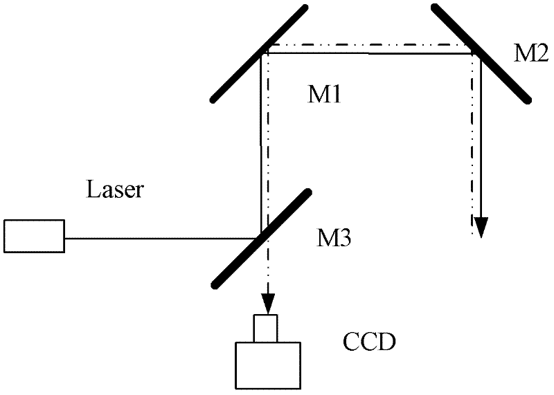
[0022] Such as figure 1 As shown, the tracking system is composed of a high-resolution small-angle fast mirror M1, a beam splitter M3, a CCD image detection system, a low-resolution large-angle fast mirror M2, and a beacon laser (Laser). All components are installed on the same platform. The optical position relationship is described as follows: the target light is reflected by the fast mirror M2 and M1 in turn, and then reaches the CCD image detection system through the beam splitter M3; Reflect to reach the target, note that the positions of M2 and M1 can be interchanged. The optical axis of the beacon laser (solid line) intersects with the detection optical axis (dashed line) at the center poin...


PUM


Abstract

The invention discloses a tracking system of a large-angle fast steering mirror. The tracking system realizes a large-angle high-precision tracking function by using a high-resolution and small-angle fast steering mirror M1 and a low-resolution and large-angle fast steering mirror M2. A control method is as follows: the closed loops of the two fast steering mirrors M1 and M2 are realized in the same optical path by using position information provided by a position detector; the two fast steering mirrors M1 and M2 deflect, but do not couple; two control ways can be adopted, wherein the first way is as follows: M1 carries out closed loop by directly using position deviation provided by a CCD (Charge Coupled Device), and a closed loop signal of M2 is the sum of the position deviation and a deflection angle of M1; the second way is as follows: the closed loop signal of M2 is the deflection angle of M1. Large-angle (namely the maximum intersection angle of M2) and high-precision tracking can be realized no matter which scheme is adopted. The control method provided by the invention enables the tracking system to be simple and can be used for improving the beam quality and the detectionprecision.

Description

technical field [0001] The invention relates to the field of light beam control, in particular to a large-angle fast mirror tracking system, which can be used in a high-precision tracking system. Background technique [0002] In many precision beam correction fields, both large-angle deflection and high-precision tracking are required, which requires fast mirrors with high closed-loop bandwidth and large-angle deflection. It is usually difficult to meet this requirement with a fast reflector. This is mainly due to the limitation of the driving mechanism of the fast mirror: the mirror driven by piezoelectric ceramics has a high response frequency and can achieve high bandwidth, but the rotation angle is limited; the mirror driven by a voice coil motor has a large range of rotation angle, but the response frequency is low, making it difficult to achieve high bandwidth. [0003] If the above two types of mirrors are combined in the optical path, the current method is to place...

Claims


Application Information

Patent Timeline
Patent Type & Authority Applications(China)
IPC IPC(8): G05D3/12G02B7/198
Inventor 唐涛任戈扈弘毅黄永梅傅承毓包启亮
Owner INST OF OPTICS & ELECTRONICS - CHINESE ACAD OF SCI
Why Eureka
Try Eureka