Nerve monitoring during electrosurgery

An electrosurgery and surgical technology, applied in the field of neuromonitoring systems, can solve the problems of troublesome and time-consuming electrosurgery

Active Publication Date: 2012-03-07
MEDTRONIC INC
View PDF4 Cites 5 Cited by
  • Summary
  • Abstract
  • Description
  • Claims
  • Application Information

AI Technical Summary

Problems solved by technology

In situations where EMG activity cannot be monitored during electrosurgery, electrosurgery can become cumbersome and time-consuming

Method used


Image

  • Nerve monitoring during electrosurgery
  • Nerve monitoring during electrosurgery
  • Nerve monitoring during electrosurgery

Examples


Embodiment Construction

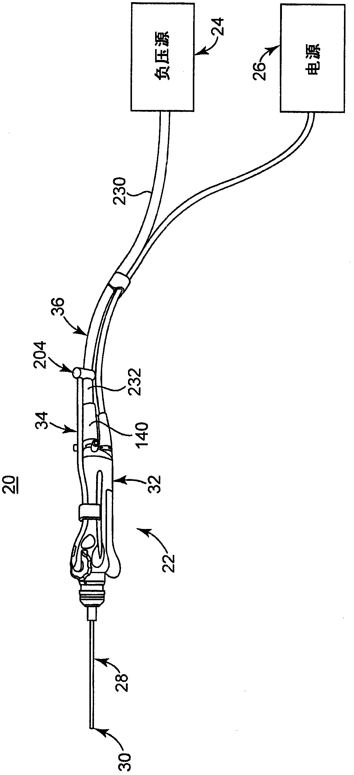
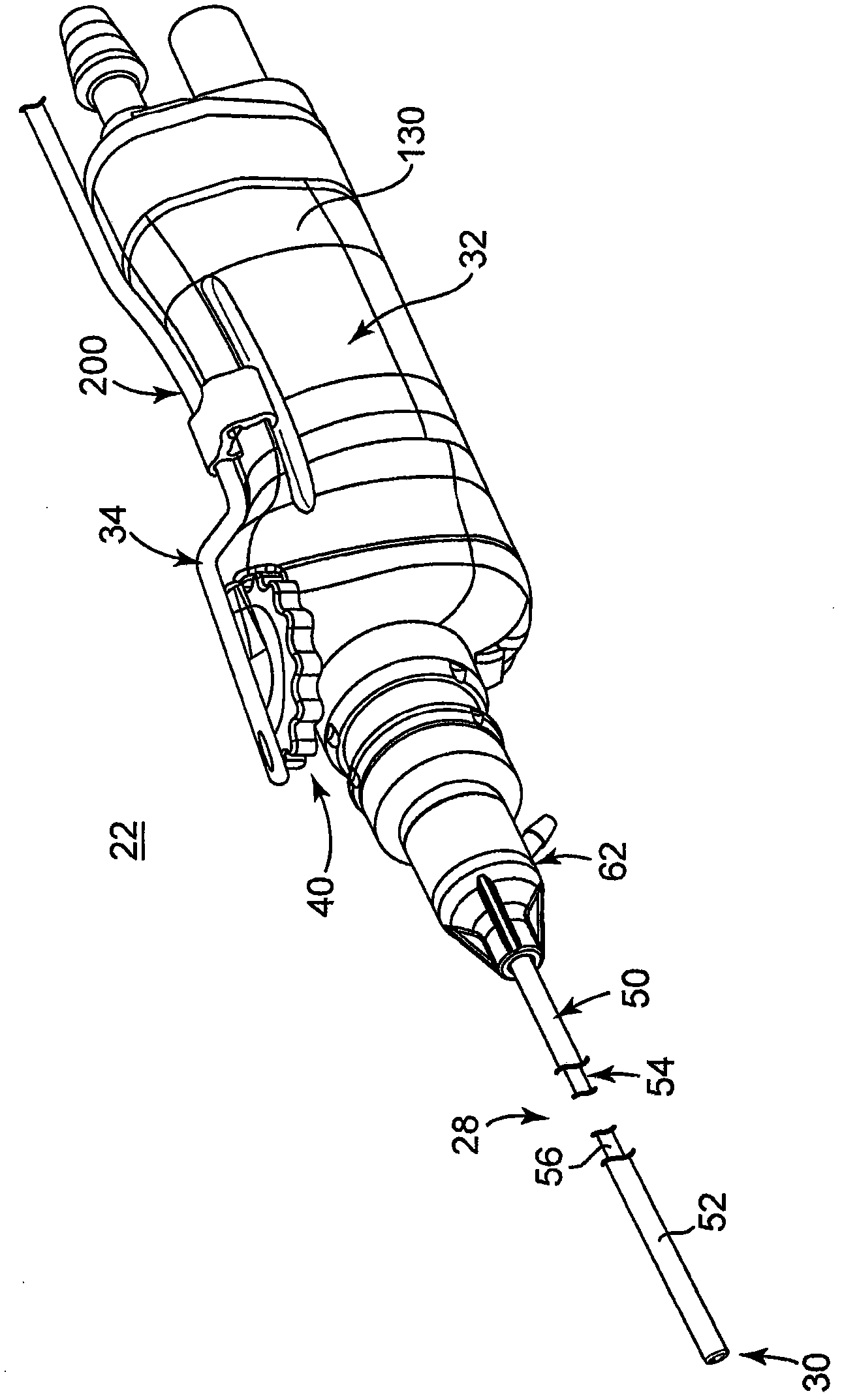
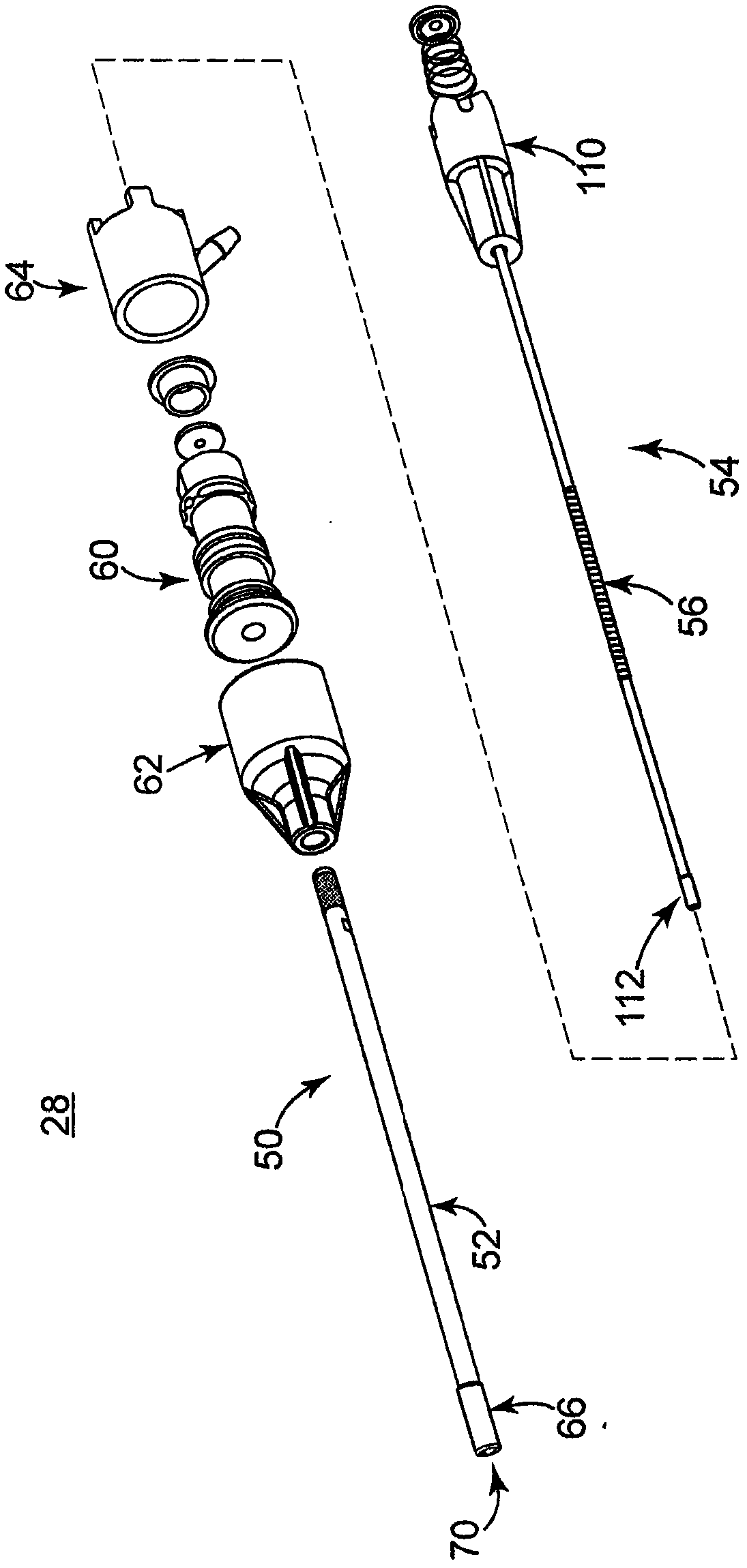
[0015] exist figure 1 A surgical environment including a nerve integrity monitoring system 10 and an electrosurgical unit (ESU) 12 is shown in . In general, system 10 is configured to facilitate and perform neural integrity monitoring of virtually any nerve / muscle combination of human anatomy, as well as recording nerve potentials. System 10 includes a control unit 20 , which may take a wide variety of forms, and in one embodiment includes a console 30 having a monitor 32 and a patient interface module 40 . Electrosurgical unit 12 includes an ESU generator 42 coupled to a surgical instrument 44 . ESU generator 42 generates electrical current that is sent to surgical instrument 44 for cutting or otherwise manipulating the patient's tissue.

[0016] System 10 includes a stimulation probe assembly 50, which may be used for electrical stimulation, and one or more sensing probes 52, which may be any type of sensing device, such as electrodes. Control unit 20 facilitates operatio...


PUM


Abstract

A signal processing module includes an input module electronically coupled to a sensing probe (52) of a nerve integrity monitoring system (10). The probe senses electrical signals from a patient during operation of an electrosurgical unit (12). The input module receives an input signal from the probe. An EMG detection module is coupled to the input module and is adapted to detect conditions in the input signal. The conditions are classified as a function of a level of electromyographic activity. An output module, coupled to the EMG detection module, provides an indication of electromyographic activity in the input signal based on the detected conditions.

Description

Background technique [0001] The present disclosure relates to neural monitoring systems. More specifically, the invention relates to monitoring neural activity during electrosurgery or in the presence of artifacts from metallic surgical instruments. [0002] Electrophysiological monitoring assists the surgeon in locating nerves within the ambiguous surgical field, as well as maintaining and assessing nerve function in real time during surgery. To this end, neural integrity monitoring is often employed to monitor electromyographic (EMG) activity. During neural integrity monitoring, sensing electrodes or recording electrodes are coupled to appropriate tissue (eg, cranial muscles innervated or controlled by nerves of interest, peripheral nerves, spinal cord, brainstem, etc.) to sense EMG activity. Stimulation, such as electrical or mechanical stimulation, can cause excitation of the tissue. During electrical stimulation, a stimulating probe applies a stimulating signal near an...

Claims


Application Information

Patent Timeline
Patent Type & Authority Applications(China)
IPC IPC(8): A61B5/0488A61B5/296
CPCA61B5/7264A61B17/32A61B5/389A61B5/7225A61B5/7203A61B5/725A61B5/7246A61B2217/002A61B5/316A61B5/7217
Inventor J·M·墨菲J·A·梅耶A·L·曼德兹K·L·麦克法林D·C·哈克尔
Owner MEDTRONIC INC
Why Eureka
Try Eureka