
Alignment adjustment method for bolt cold heading machine and mold box positioning mold

A cold heading machine and mold box technology, applied to bolts, manufacturing tools, threaded fasteners, etc., can solve problems such as difficulty in meeting high density requirements, poor product quality assurance, complex structure of cold heading machines, etc., and achieve high yield High, shortened motion length, precise and stable adjustment effect

Inactive Publication Date: 2015-09-23
郭朝阳
View PDF6 Cites 0 Cited by
  • Summary
  • Abstract
  • Description
  • Claims
  • Application Information

AI Technical Summary

Problems solved by technology

Since it requires three times of cold heading, and the mold frame holes are different for each cold heading, it is necessary to take out the semi-finished product from the mold frame hole and put it into another mold frame hole. The traditional method of workpiece displacement adopts "clamp box" ( Equivalent to a manipulator), this kind of cold heading machine has complex structure, high failure rate, long transposition time, and low work efficiency; there is another method that uses a rotating mold box, through the rotation and transposition positioning of the mold box, to realize workpiece machining. This method not only has high efficiency, but also has a relatively simple mechanical structure. However, there is a problem that has always troubled people, that is, the positioning of the mold box, due to the frequent rotation of the mold box, the slight error caused by the gear drive mechanism, The error of the hole corresponding to the manufacturing mold box, the error of the installation mold and the instability of the mold box result in a high reject rate of the manufactured bolts, it is difficult to meet the high-density processing, and the product quality is not guaranteed.

Method used


Image

  • Alignment adjustment method for bolt cold heading machine and mold box positioning mold
  • Alignment adjustment method for bolt cold heading machine and mold box positioning mold
  • Alignment adjustment method for bolt cold heading machine and mold box positioning mold

Examples


Embodiment Construction

[0023] The present invention is described in further detail below in conjunction with accompanying drawing:

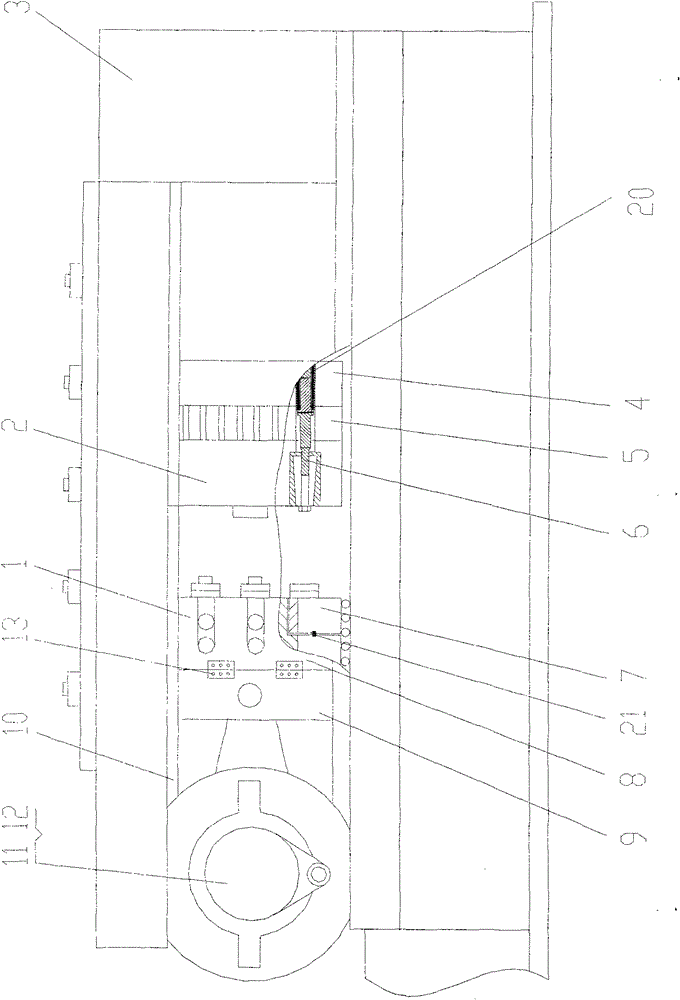
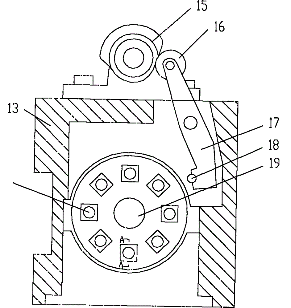
[0024] The basic structure of the bolt cold heading machine of the present invention is as follows: figure 1 As shown, it includes a body 3, a heading slider 1, a mold box 2, and a driving mechanism 11. The heading slider 1 is located in the slideway 10 in the body 3, and is connected between the crankshaft connecting rod 12 and the driving mechanism 11. The mold The box 2 is located on the opposite side of the heading slider 1, and is fixed on the supporting shaft 19 of the body 3 through bearings. The supporting shaft is also equipped with a gear 5 and a positioning wheel 4. The positioning wheel 4 is on the innermost side, and the gear 5 is in the middle. The positioning wheel 4, the gear 5 and the mold box 2 are fastened together to form a whole, the gear 5 is connected with the driving mechanism 11, and the positioning wheel 4 is connected with the driving mechani...


PUM


Abstract

The invention discloses a bolt cold header, a mould box thereof and a correcting and adjusting method for positioning a mould. The bolt cold header comprises a machine body, a head sliding block, a mould box and a driving mechanism. In the bolt cold header, the mould and the mould box are separated, the mould placed in the mould box is finely adjusted and positioned and a fine adjusting positioning method is used for positioning and adjusting the mould box, thereby completely and accurately aligning the mould with the head, being accurate in positioning, and being high in quality precision of products and high in yield. The head sliding block is improved and is changed into an opening type head, thereby facilitating the replacement of a mould head. The correcting and adjusting method is also performed on the mould head. The opening type head can be used for greatly reducing the crank axle length of a crank shaft connecting rod, increasing an operating torsion and achieving an excellent effect.

Description

technical field [0001] The invention relates to a bolt manufacturing equipment, in particular to a bolt cold heading machine and a method for aligning and adjusting a mold box positioning mold. Background technique [0002] The basic structure of the existing bolt cold heading machine is composed of the heading slider driven by the crankshaft connecting rod mechanism and the corresponding mold box. There are corresponding bolt mold frame holes on the mold box and the heading head, generally three , the bolts are formed by three cold headings. Since it requires three times of cold heading, and the mold frame holes are different for each cold heading, it is necessary to take out the semi-finished product from the mold frame hole and put it into another mold frame hole. The traditional method of workpiece displacement adopts "clamp box" ( Equivalent to a manipulator), this kind of cold heading machine has complex structure, high failure rate, long transposition time, and low w...

Claims


Application Information

Patent Timeline
Patent Type & Authority Patents(China)
IPC IPC(8): B21J5/06B21J13/03B21K1/44
Inventor 郭朝阳
Owner 郭朝阳
Learn More