
Paperboard dividing and cutting machine

A technology of slitting machine and cardboard, which is applied in the direction of metal processing, etc., can solve the problems of high price units of automatic die-cutting machines, large size and specification errors of finished products, and inability to meet mass production, so as to avoid die-cutting efficiency Low cost, improved cutting efficiency, and reduced auxiliary adjustment time

Active Publication Date: 2014-04-16
浙江浩达智能装备股份有限公司
View PDF6 Cites 0 Cited by
  • Summary
  • Abstract
  • Description
  • Claims
  • Application Information

AI Technical Summary

Problems solved by technology

[0002] At present, there are two cutting processes for hardcover bookcases, desk calendars, file folders and other inner core cardboards: one is cutting by a paper cutter. Because the density of the cardboard is high, the material is thicker and thicker, and the upper layer is cut every time it is cut. There is a large difference in size between the gray board and the bottom gray board (commonly known as "floating knife"), the angle ruler is not accurate, and the production efficiency is not high, which cannot meet the requirements of mass production, and the size and specification error of the finished product is large, which directly affects to product quality
The second is to use a die-cutting machine to die-cut, that is, to make a laser knife die and carry out die-cutting processing on a die-cutting machine. It is necessary to make a die for each specification, which greatly increases the auxiliary cost of production.
The semi-automatic die-cutting machine can only die-cut one gray board at a time, and its work efficiency is extremely low
However, the high price and huge unit of the automatic die-cutting machine make many manufacturers give up this scheme.

Method used


Image

  • Paperboard dividing and cutting machine
  • Paperboard dividing and cutting machine
  • Paperboard dividing and cutting machine

Examples


Embodiment Construction

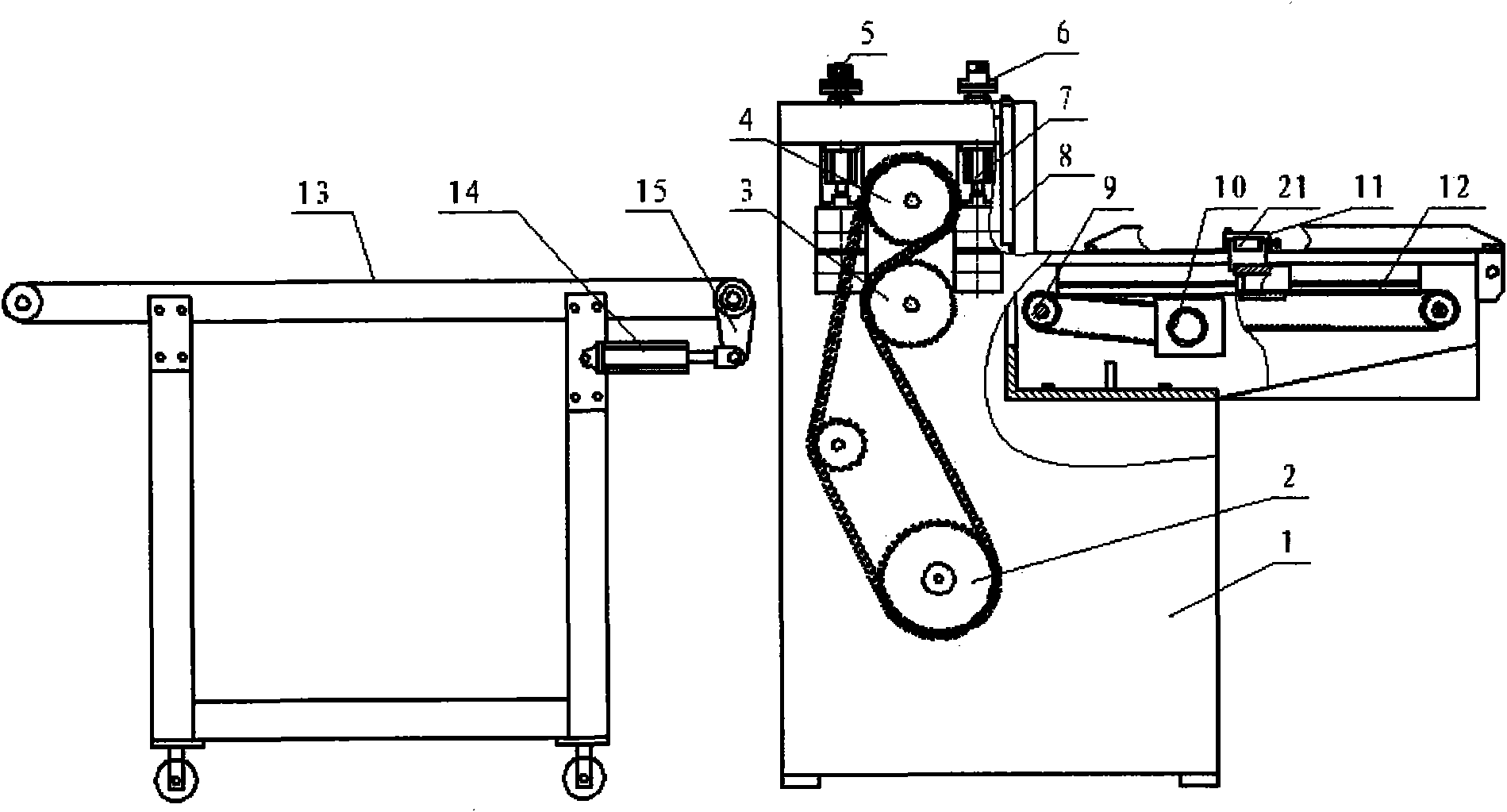
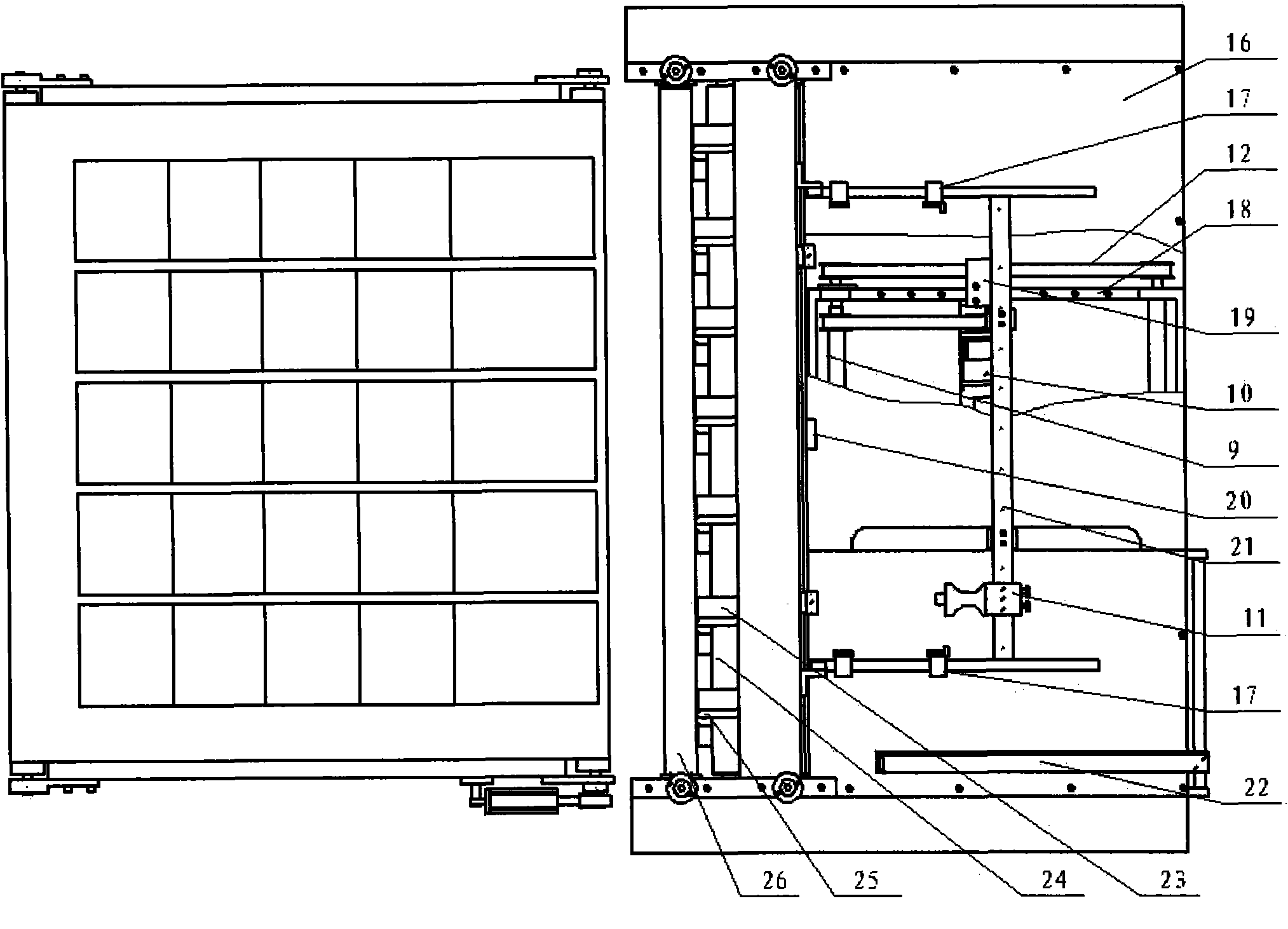
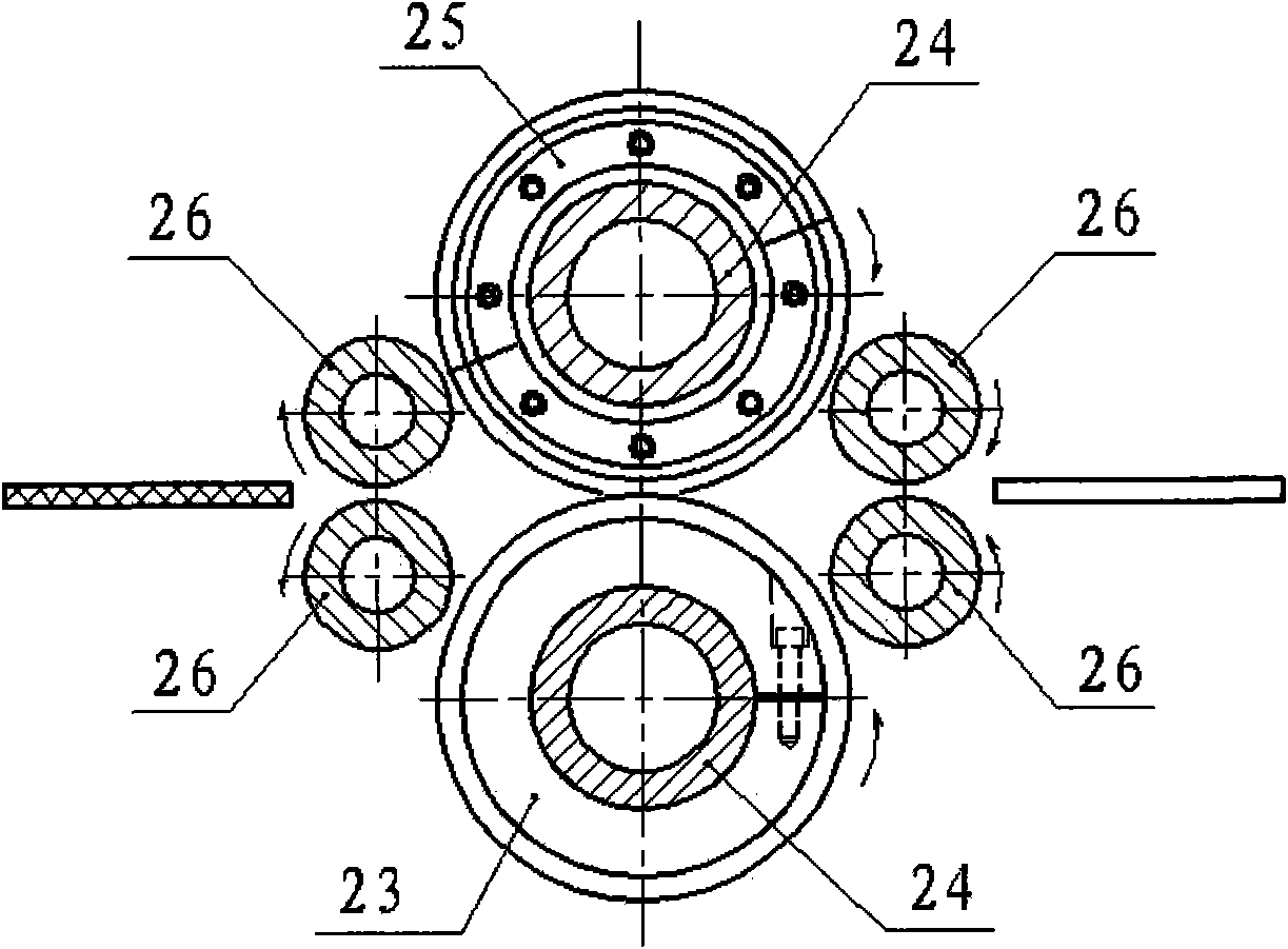
[0027] Next, the cardboard slitting machine of the present invention will be described in detail below with reference to the accompanying drawings.

[0028] The cardboard slitting machine of the present invention comprises a frame, a paper guide mechanism on the frame, and a paper cutting mechanism, the paper cutting mechanism is on one side of the paper guiding mechanism in the horizontal direction, and the paper cutting mechanism is arranged behind There is a paper delivery mechanism, and the paper guide mechanism sends the paper to be cut into the paper cutting mechanism for cutting, and finally the paper delivery mechanism gathers the cut paper. A thickness adjusting device is also arranged above the paper cutting mechanism. The thickness adjustment device includes a thickness adjustment cylinder, a thickness adjustment locking screw, and a thickness adjustment pad. The thickness adjustment cylinder drives the thickness adjustment locking screw and the thickness adjustment...


PUM


Abstract

The invention discloses a paperboard dividing and cutting machine, which comprises a machine frame, a paper guiding mechanism and a paper dividing and cutting mechanism. The paper guiding mechanism and the paper dividing and cutting mechanism are arranged on the machine frame. The paper dividing and cutting mechanism is at one side of the paper guiding mechanism in horizontal direction. A paper collecting mechanism is arranged at the rear of the paper dividing and cutting mechanism. The paper guiding mechanism is used for feeding paper to be divided and cut into the paper dividing and cutting mechanism to divide and cut. Finally, the divided and cut paper is collected through the paper collecting mechanism. The paperboard dividing and cutting machine can be applied to effectively and precisely dividing and cutting paperboards. The paperboard dividing and cutting machine is rational in structural design, convenient for adjustment, high-speed in dividing and cutting efficiency (the highest speed can be up to 120 m / min) and ultra-high in dividing and cutting precision. The disadvantages of non-uniform dividing and cutting size, low production efficiency and the like in the current paperboard dividing and cutting machine can be thoroughly solved.

Description

technical field [0001] The invention relates to a cardboard slitter, in particular to a cardboard slitter with high efficiency, low cost and precise cutting. Background technique [0002] At present, there are two cutting processes for hardcover bookcases, desk calendars, file folders and other inner core cardboards: one is cutting by a paper cutter. Because the density of the cardboard is high, the material is thicker and thicker, and the upper layer is cut every time it is cut. There is a large difference in size between the gray board and the bottom gray board (commonly known as "floating knife"), the angle ruler is not accurate, and the production efficiency is not high, which cannot meet the requirements of mass production, and the size and specification error of the finished product is large, which directly affects to product quality. The second is to use a die-cutting machine to die-cut, that is, to make a laser knife die and carry out die-cutting processing on a die...

Claims


Application Information

Patent Timeline
Patent Type & Authority Patents(China)
IPC IPC(8): B26D1/24B26D7/06B26D7/26
Inventor 孙超叶芳
Owner 浙江浩达智能装备股份有限公司
Learn More