Steel trussed beam and flexible arch bridge construction method with vault pushing

A construction method and technology of steel truss girder, applied in the direction of bridges, bridge construction, erection/assembly of bridges, etc., can solve the problems of large span, high cost, and difficult operation of steel bridges, and achieve centralized assembly operation sites and roof lifting. The effect of small displacement value and reduced operating time

Active Publication Date: 2012-03-14
CHINA TIESIJU CIVIL ENG GRP CO LTD +1
View PDF5 Cites 34 Cited by
  • Summary
  • Abstract
  • Description
  • Claims
  • Application Information

AI Technical Summary

Problems solved by technology

However, continuous provision of temporary piers in the middle of the expressway cannot pass the traffic safety assessment
[0006]2. Temporary piers are used to assist two-way cantilever construction to close the middle of the span. It is necessary to construct large foundations for temporary supports on the shoulders on both sides of the expressway, and road and driving safety cannot be guaranteed.
[0007]3. The sling tower assists two-way cantilevered mid-span closure, and there is no need to set up temporary piers within the expressway limit, but the sling tower is a huge Special equipment, complex structure, high cost
[0008]4. The above three schemes need to hang rods above the expressway. The safety protection of road-related construction is complex and changeable, and it is difficult to guarantee the operation safety of the expressway
[0010]1. Due to the large span of the steel bridge and the downward deflection caused by the self-weight of the steel truss girder, it is necessary to adjust the alignment of the steel girder by jacking up the girder and prevent the steel truss girder from Instability of members and local overstress, complicated strengthening measures
[0011]2. The mid-span closure scheme of the beam first and then the arch needs to be operated at a height of 75m above the expressway, which is difficult to operate and has high safety risks

Method used


Image

  • Steel trussed beam and flexible arch bridge construction method with vault pushing
  • Steel trussed beam and flexible arch bridge construction method with vault pushing
  • Steel trussed beam and flexible arch bridge construction method with vault pushing

Examples


Embodiment Construction

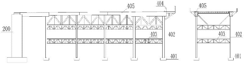
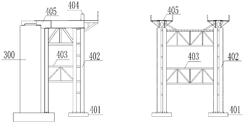
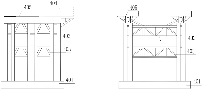
[0047] Referring to the accompanying drawings, according to the calculation and analysis of the working condition of the vaulted roof, it is necessary to set up temporary supports for steel bridge erection and jacking construction, and to set up multi-span assembly supports 410 at the side-span main pier 200 assembly yard, the middle-span main pier 300 and the other side A bracket 420 next to the pier is set at the main pier 200, and a temporary pier bracket 430 is set in the middle of the span.

[0048] The structure of the assembly bracket 410 is as follows figure 1 As shown, the structure of the bracket 420 next to the pier is as follows figure 2 As shown, the structure of the temporary pier support 430 in the middle span of the main span is as follows: image 3 shown. The lower part of the steel pipe column 402 is a pile foundation cap 401, and the columns are connected by a pipe truss 403. A steel box structure slideway beam 405 is installed on the top surface of the s...


PUM


Abstract

The invention discloses a steel trussed beam and flexible arch construction method with vault pushing, which comprises the following steps of: building an assembly support in the side span of a steel trussed beam, assembling a guide beam and the steel trussed beam into an integral space on the assembly support, arranging a horizontal continuous jack and a mechanical, electrical and hydraulic control system on the assembly support, pushing the steel trussed beam forward by using the horizontal jack, and continuing next round of assembly work on the rear assembly support whenever one round is pushed forward. By using the steel trussed beam and flexible arch construction method with vault pushing provided by the invention, the steel trussed beam and the flexible arch are erected outside the operating limit of a highway, and the construction difficult across the highway is solved.

Description

technical field [0001] The invention specifically relates to a steel truss flexible arch bridge with vault push construction method, which is particularly suitable for the erection construction of large-span continuous steel truss flexible arch bridges spanning highways, railways and rivers, and belongs to the technical field of bridge construction. Background technique [0002] As a structural type of long-span steel truss bridges, flexible arch bridges with steel truss girders have the advantages of large vertical rigidity, clear structural stress, novel design, and beautiful architectural shapes. They are used in some bridges spanning highways, railways, and rivers. . At present, the construction methods of long-span steel truss girder flexible arch bridges are mostly two-way cantilever assembly, middle closing, and beam-first arching methods. According to its structural characteristics, environmental factors, and boundary conditions, construction auxiliary facilities an...

Claims


Application Information

Patent Timeline
Patent Type & Authority Applications(China)
IPC IPC(8): E01D21/06
Inventor 方继夏阳张庆发杨慧丰张雪松张时利陈宝民刘瑜史纲
Owner CHINA TIESIJU CIVIL ENG GRP CO LTD
Why Eureka
Try Eureka