Box body lining type mudslide discharging and guiding groove and application and construction method thereof

A technology for draining guide troughs and debris flow, which is applied in botany equipment and methods, water conservancy projects, artificial waterways, etc. It can solve problems such as high maintenance costs, damage to the bottom of guide troughs, and failure to use normally, so as to reduce later maintenance The cost, the post-maintenance cost reduction, and the effect of shortening the construction period

Active Publication Date: 2012-03-14
INST OF MOUNTAIN HAZARDS & ENVIRONMENT CHINESE ACADEMY OF SCI
View PDF4 Cites 18 Cited by
  • Summary
  • Abstract
  • Description
  • Claims
  • Application Information

AI Technical Summary

Problems solved by technology

[0004] The purpose of the present invention is to solve the deficiencies of the prior art, and to solve the situation that the strong abrasion and scouring action of the debris flow often causes serious damage to the bottom of the drainage channel, cannot be used normally, and the maintenance cost is high i

Method used


Image

  • Box body lining type mudslide discharging and guiding groove and application and construction method thereof
  • Box body lining type mudslide discharging and guiding groove and application and construction method thereof
  • Box body lining type mudslide discharging and guiding groove and application and construction method thereof

Examples


Embodiment 1

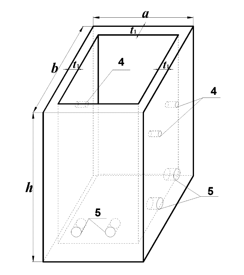
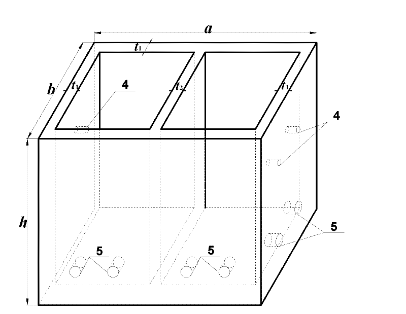
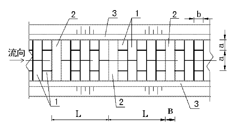
[0032] Such as figure 1 , figure 2 , image 3 , Figure 4 shown. The drainage area of ​​a debris flow ditch is 1.5km 2 , in order to control debris flow disasters, it is planned to set up 5 Gufang, 2 sand dams and 400m drainage channels in the middle of the basin. For the row guide groove, the following construction methods are adopted:

[0033] The first step is to plan and design a debris flow drainage channel with a width of 5.0m at the bottom of the channel and a vertical gradient i of 0.50 according to the situation of the debris flow channel. Since the vertical slope i≥0.15 of the row of guide grooves, it is planned to adopt the box-lined debris flow drainage groove of the present invention. The box-lined debris flow drainage channel includes the bottom of the drainage channel and the side walls 3 of the drainage channel on both sides. There are several levels of energy-dissipating sills distributed in steps in between, and each level of energy-dissipating sills ...

Embodiment 2

[0042] Such as figure 1 , figure 2 , image 3 , Figure 4 shown. The same as Embodiment 1 will not be repeated, the difference is: for the debris flow ditch drainage area 5.6km 2 , it is planned to set up 12 valley squares, 6 sand retaining dams and 800m drainage channels in the middle of the basin. For the row guide groove, the following construction methods are adopted:

[0043] The first step is to plan and design a debris flow drainage channel with a bottom width of 7.5m and a vertical gradient i of 0.15 according to the conditions of the debris flow ditch.

[0044] According to the vertical gradient i of the trench bed at the bottom of the trench, the parameters of rib sill 2 are planned: the distance L between the upstream and downstream rib sill 2 is 20m, the foundation depth H of rib sill 2 is 2.5m, and the width B of rib sill 2 along the longitudinal slope is 2.0 m; rib sill 2 is a reinforced concrete structure with a reinforcement ratio of 0.5%; the top 0.1m o...


PUM

PropertyMeasurementUnit
Heightaaaaaaaaaa
Diameteraaaaaaaaaa
Thicknessaaaaaaaaaa

Abstract

The invention discloses a box body lining type mudslide discharging and guiding groove suitable for mudslide with great longitudinal river slope of a gully bed, and an application and construction method thereof. The discharging and guiding groove comprises a groove bottom and side walls at two sides of the discharging and guiding groove, wherein the groove bottom comprises a transverse penetrating type ribbed threshold and a plurality of stages of baffle sills which are filled between an upstream ribbed threshold and a downstream ribbed threshold and are distributed in a stepped shape; each-stage baffle sill is formed by connecting a plurality of prefabricated reinforced concrete rectangular box bodies along the direction of the transversely penetrating the discharging and guiding groove; the top surface of each rectangular box body is opened; other five surfaces of each rectangular box body are closed; and each rectangular box body is filled with soil mass. Compared with the prior art, mutual action between the soil mass filled in the rectangular box bodies and the mudslide is used to consume the movement kinetic energy of part of the mudslide, regulate and control the flow speed of the mudslide and control the corrosion and the scouring of the mudslide to the groove bottom, so that the safety of the discharging and guiding groove is improved and the later-stage maintenance expense is reduced; compared with a full-lining type groove, the box body lining type mudslide discharging and guiding groove has the construction period shortened by 10-30 percent and the later-stage maintenance expense reduced by 50-80 percent; and compared with a soft-foundation energy dissipation type groove, the box body lining type mudslide discharging and guiding groove has the later-stage maintenance expense reduced by 30-50 percent.

Description

technical field [0001] The invention relates to a mud-rock flow prevention technology, in particular to a box-lined mud-rock flow drainage guide groove suitable for a large ditch bed vertical gradient and a construction method thereof. Background technique [0002] Debris flow disaster is one of the main types of geological disasters in my country. With the development of the mountainous economy and the deepening of the western development, the demand for debris flow control is becoming more and more vigorous. As one of the main types of debris flow prevention and control engineering, drainage channels are widely used in debris flow control. [0003] After the Wenchuan Earthquake, a large number of landslides provided a rich source of solid matter for the formation of debris flows, and a large number of debris flows in ultra-small watersheds and slope debris flows occurred. The vertical gradient of this type of debris flow is very large, generally exceeding 0.15. Even up t...

Claims


Application Information

Patent Timeline
IPC IPC(8): E02B5/00E02B5/02E02B5/08A01G9/02
CPCE02B5/02E02B8/06
Inventor 陈晓清游勇李德基崔鹏杨东旭
Owner INST OF MOUNTAIN HAZARDS & ENVIRONMENT CHINESE ACADEMY OF SCI
Why Eureka
Try Eureka