
Display unit brightness correcting method

A technology of display unit and calibration method, which is applied in the direction of static indicators, cathode ray tube indicators, instruments, etc., can solve the difference between the debugging effect and the human naked eye observation effect, the high cost of brightness and chromaticity calibration and debugging of the display unit, and the engineering personnel. It is inconvenient to carry the instrument, etc., to solve the problem of uneven brightness and chromaticity, maintain optimization, and reduce brightness loss

Active Publication Date: 2012-03-14
HUAWEI TEHCHNOLOGIES CO LTD
View PDF4 Cites 16 Cited by
  • Summary
  • Abstract
  • Description
  • Claims
  • Application Information

AI Technical Summary

Problems solved by technology

[0004] The invention overcomes the disadvantages of high cost of brightness and chromaticity calibration and debugging of the display unit in the prior art, and it is inconvenient for engineering personnel to carry the instrument, difficult to operate, and the debugging effect is different from the human naked eye observation effect, and provides a large-screen splicing display Brightness and chromaticity uniformity calibration method of display unit in the system

Method used


Image

  • Display unit brightness correcting method
  • Display unit brightness correcting method
  • Display unit brightness correcting method

Examples


Embodiment Construction

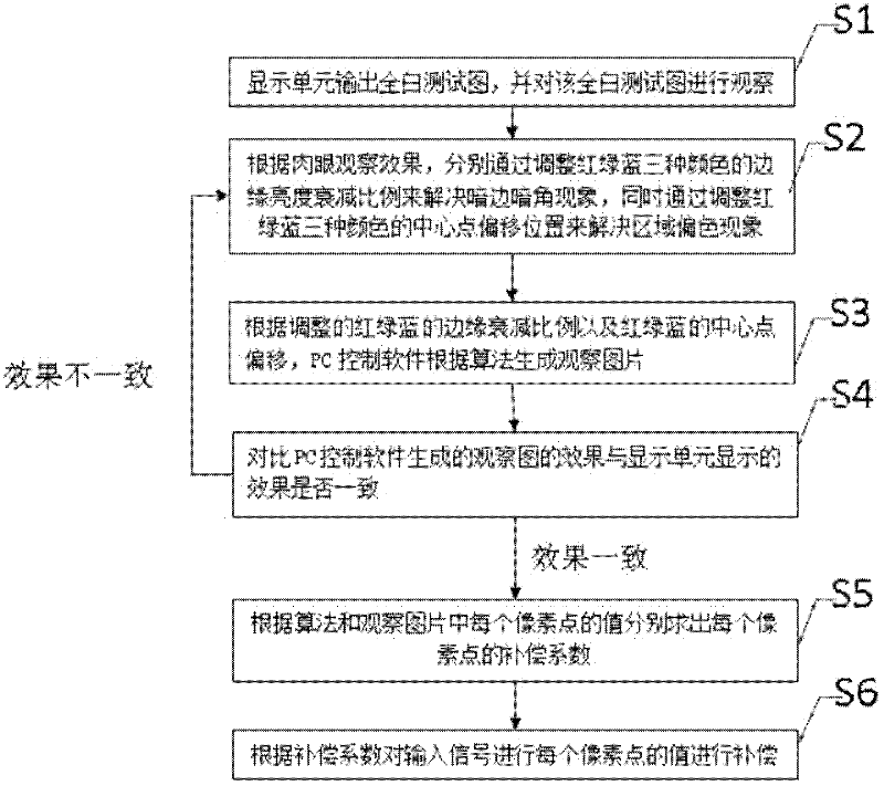
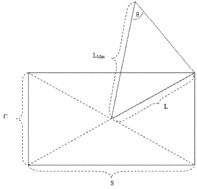
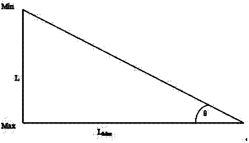
[0023] The method of the present invention is mainly algorithm control, and the main method is the data algorithm of image generation, adjusting the ratio of edge brightness reduction and the red, green, and blue center point positions of projection light sources according to the comparison effect between the all-white test image displayed on the display unit and the generated image. Its core idea is to simulate the display effect of the display unit according to the algorithm (including the uneven optical path, the inconsistency and offset of the red, green and blue center points of the projected light source), and generate an observation map, and use the observation map as a reference to generate each pixel through the algorithm Point compensation coefficient. At the same time, due to the generation of observation pictures for simulating display effects, the data generation algorithm used is the cosine fourth power law of Lambert radiator, and it is accurate to each display p...


PUM


Abstract

The invention provides a display unit brightness correcting method. According to the invention, the method comprises the following steps of: (S1) outputting an all white test chart and observing the all white test chart; (S2) adjusting edge brightness attenuation ratio and central point offset positions of red, green and blue colors; (S3) generating an observing image according to the adjusted edge attenuation ratio of the red, green and blue colors and central point offset of the red, green and blue colors; (S4) comparing whether the effect of an observation chart generated by PC control software is consistent with the effect displayed by the display unit or not; and if so, executing the step 5; and if not so, continuing to execute the step 2; (S5) figuring out the compensation factor ofeach pixel point; and (S6) compensating the value of each pixel point of an input signal according to the compensation factor. According to the invention, the defects of high cost in correcting and debugging the brightness of the display unit, inconvenience for engineer to carry the instrument, difficulties in operation and difference between the debugging effect and human naked eye observation effect in the prior art are overcome.

Description

technical field [0001] The invention relates to the technical field of image display processing, in particular to a method for calibrating brightness and chromaticity of a display unit. Background technique [0002] In the field of large-screen spliced ​​display systems, the display technologies used in the composed spliced ​​display units are usually projection display technology and flat panel display technology. Among them, in the projection display technology, due to the non-uniformity of the light path from the projection light source to each pixel of the screen and the misalignment of the center points of the red, green and blue primary colors of the projection light source, the image displayed by the display unit will have uneven brightness and chromaticity. Such as dark edges and dark corners, color cast in a certain area relative to other areas, etc.; and in the flat panel display technology, due to the uneven distribution of the background light source used, the im...

Claims


Application Information

Patent Timeline
IPC IPC(8): G09G5/02G09G5/10G09G3/20
Inventor 彭春山黄少飞
Owner HUAWEI TEHCHNOLOGIES CO LTD
Learn More