

Vacuum oiling device for transformer
A technology for oil injection device and transformer, applied in the direction of transformer/inductor cooling, etc., can solve the problems of endangering the use safety of transformers, causing pollution flashover due to sticky dust, easy to form pollution flashover, etc., to ensure normal operation, convenient centralized cleaning, and good insulation. effect of action
Inactive Publication Date: 2012-03-14
JIANGSU SHENGHUA ELECTRIC
View PDF0 Cites 0 Cited by
- Summary
- Abstract
- Description
- Claims
- Application Information
AI Technical Summary
Problems solved by technology
[0002] Because air bubbles are more harmful to transformers, especially if there is air in transformers used in high-voltage environments, partial discharges will occur. Therefore, vacuum oiling is used to discharge the air in the transformers. When vacuum oiling, put the transformer as a whole into a vacuum. In the tank, the transformer oil will be atomized in a vacuum state, so the oil mist will adhere to the appearance of the transformer and the connection holes and gaps to form residual oil, and the residual oil will stick to the surface and cause pollution flashover, so it must be removed Clean the residual oil. As time goes by, the residual oil remaining in the connection hole will seep out and form oil stains. After the oil stain and dust adhere, it is easy to form pollution flashover under high voltage, which will affect the performance of the transformer. Performance may even endanger the safety of the transformer
Method used
View moreImage
Smart ImageViewing Examples


Examples
Embodiment Construction
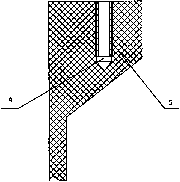
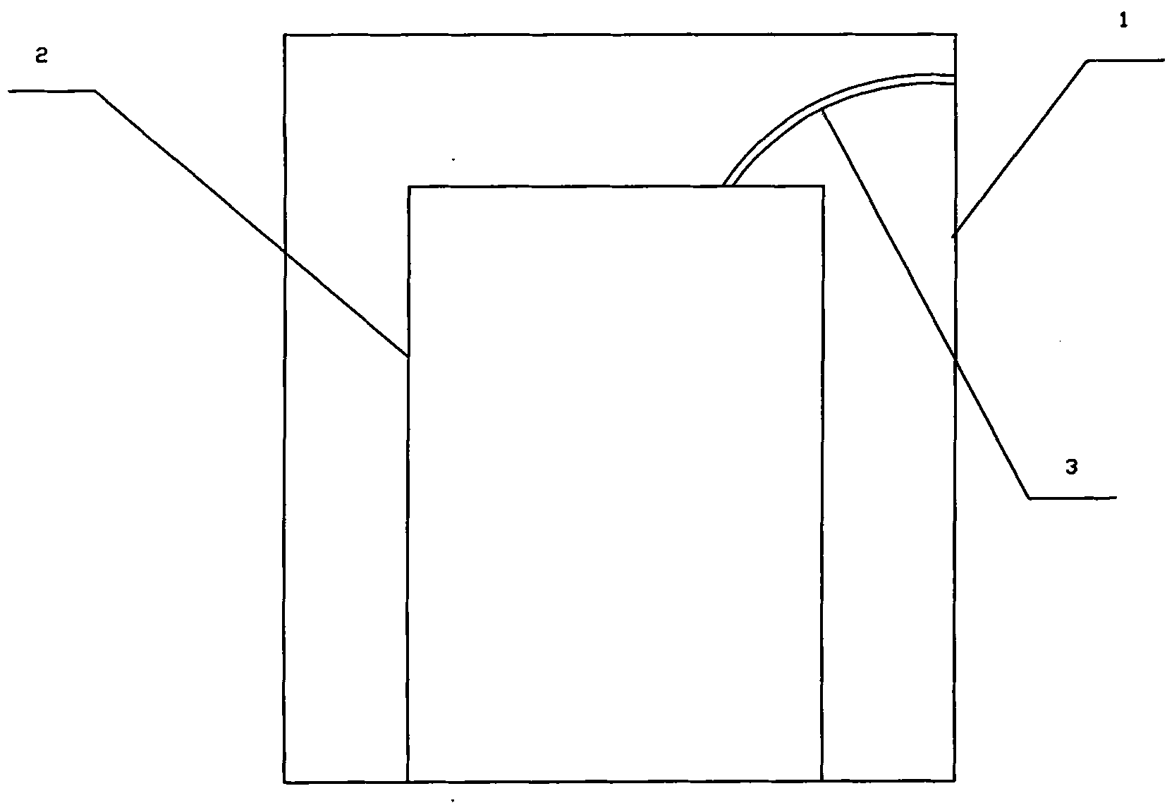
[0010] A transformer vacuum oiling device, the transformer 2 is placed in a vacuum tank 1 as a whole, a threaded blind hole 4 is drilled on the flange end face of the insulating cylindrical transformer 2, and a threaded silicon sleeve 5 is arranged in the blind hole 4 .
Login to View More PUM
 Abstract
The invention relates to a vacuum oiling device for a transformer. The transformer is entirely arranged in a vacuum tank; a tapped blind hole is drilled on the end face of the flange of the insulating cylinder-type transformer; and a threaded silicone jacket is arranged in the blind hole. In the vacuum oiling device for the transformer, the tapped blind hole is drilled on the end face of the flange of the insulating cylinder-type transformer, thus, oil mist can be gathered in the blind hole; with the time extension, residual oil remaining in the hole cannot seep, centralized clearing is facilitated, and pollution flashover formed after oil stains and dust are adhered under the high-pressure state is also avoided, thereby, the normal operation of the transformer equipment is ensured. The threaded silicone jacket is arranged in the blind hole, thus, the strength of the blind hole can be increased, and a better insulating action is performed.
Description
technical field [0001] The invention relates to a transformer vacuum oiling device. Background technique [0002] Because air bubbles are more harmful to the transformer, especially if there is air in the transformer used in a high-voltage environment, partial discharge will occur. Therefore, the air in the transformer is discharged by vacuum oiling. When vacuum oiling, the transformer is put into a vacuum In the tank, the transformer oil will be atomized in a vacuum state, so the oil mist will adhere to the surface of the transformer and the connection holes and gaps to form residual oil, and the residual oil will stick to the surface and cause pollution flashover, so it must be removed Clean the residual oil. As time goes by, the residual oil in the connection hole will seep out and form oil stains. After the oil stains and dust adhere, it is easy to form pollution flashover under high voltage, which will affect the performance of the transformer. The use performance will...
Claims
Login to View More Application Information
Patent Timeline
 Patent Type & AuthorityApplications(China)
IPC IPC(8): H01F27/14
Inventor黄天顺
OwnerJIANGSU SHENGHUA ELECTRIC