Carbon heating structure having flange type structure and heating device
A technology for heating devices and structures, applied in electric heating devices, heating elements, ohmic resistance heating, etc., can solve the problems of difficult installation, waste of time, incompatibility, etc., and achieve easy installation and replacement, wide application range, and convenient installation. Effect
- Summary
- Abstract
- Description
- Claims
- Application Information
AI Technical Summary
Problems solved by technology
Method used
Image

Examples
Embodiment Construction
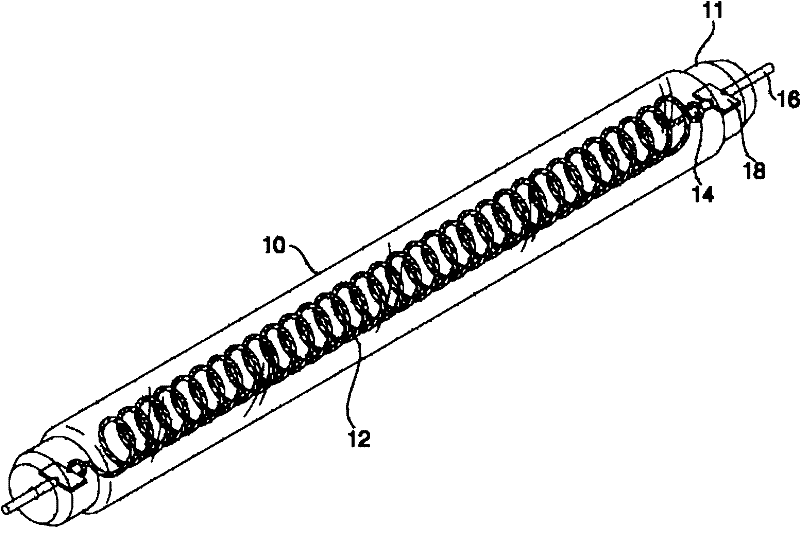
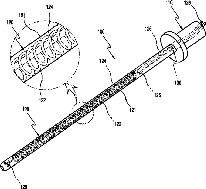
[0058] In order to achieve the above object, the present invention mainly forms a certain space in a rod-shaped quartz tube sealed at one end, in which a carbon fiber heating element and a carbon heating element inserted into the inner quartz tube are arranged in the space, and there is also a detachable one in a vacuum state. The flange, where the power supply part is only at one end, generates heat and supplies electricity for the carbon thermal structure. Through this structure, a carbon thermal structure with a flange structure and a heating device with the carbon thermal structure are formed to realize the present invention.
[0059] The specific embodiment of the present invention is shown in the figure, and will be described in detail below.
[0060] It is emphasized here that the terms or vocabulary used in this specific embodiment and the scope of the claims cannot be interpreted according to the meaning of the dictionary in the usual sense. The inventor can define the...
PUM
 Abstract
Description
Claims
Application Information
 - Generate Ideas
- Intellectual Property
- Life Sciences
- Materials
- Tech Scout
- Unparalleled Data Quality
- Higher Quality Content
- 60% Fewer Hallucinations
Browse by: Latest US Patents, China's latest patents, Technical Efficacy Thesaurus, Application Domain, Technology Topic, Popular Technical Reports.
© 2025 PatSnap. All rights reserved.Legal|Privacy policy|Modern Slavery Act Transparency Statement|Sitemap|About US| Contact US: help@patsnap.com