Method and device for recycling waste heat of steam

A waste heat recovery device and water vapor technology, applied in cooking utensils, household appliances, applications, etc., can solve the problems of taking away heat energy and increasing the temperature of the kitchen working environment, and achieve the effects of reducing heat energy loss, simple structure, and high efficiency

Inactive Publication Date: 2014-07-23
MIDEA GRP CO LTD
View PDF6 Cites 0 Cited by
  • Summary
  • Abstract
  • Description
  • Claims
  • Application Information

AI Technical Summary

Problems solved by technology

Although the steaming cabinet can improve the utilization rate of heat energy; however, the steam entering the steaming room is directly discharged into the kitchen after heating the food, which not only greatly increases the working environment temperature of the kitchen; at the same time, the waste steam takes away a large part of the thermal energy

Method used


Image

  • Method and device for recycling waste heat of steam
  • Method and device for recycling waste heat of steam
  • Method and device for recycling waste heat of steam

Examples


Embodiment Construction

[0014] Below in conjunction with embodiment do further explanation.

[0015] The water vapor waste heat recovery method of the present invention recovers part or all of the water vapor used in the circulating heating system to the thermal energy converter, and the air in the thermal energy converter is heated and then drawn out from the thermal energy converter.

[0016] Part or all of the heated air drawn from the heat energy converter is sent back to the circulating heating system.

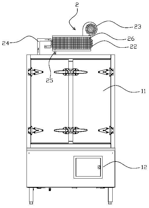
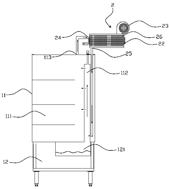
[0017] The structural representation of the steam waste heat recovery device of the present invention is as follows: figure 1 , figure 2 As shown, it includes an upper cabinet 11 and a lower cabinet 12. The upper cabinet 11 includes a number of independent steaming chambers 111. A steamer 121 is arranged in the lower cabinet 12. A heater is installed on the side of the steamer 121. , the steamer 121 communicates with the steam chamber 111 through the steam delivery pipe 112, the heat energy c...


PUM


Abstract

The invention provides a method and a device for recycling waste heat of steam. The method for recycling waste heat of the steam in the invention comprises the following steps: partially or completely recycling the steam in a circulation heating system after being used to a thermal energy converter; and leading the air out from the thermal energy converter after the air in the thermal energy converter is heated and the temperature of the air is risen. The device for recycling waste heat of the steam in the invention adopts the waste heat of the steam to heat the air in the thermal energy converter by the thermal energy converter, and conveys the air after being heated to a steam box of food by a fan so that the waste heat of the steam is reused and the loss of thermal energy is reduced.

Description

technical field [0001] The invention relates to the field of kitchen food processing equipment, in particular to a water vapor waste heat recovery device. Background technique [0002] The steam cabinet occupies a very important position in the hotel equipment, and it is also the equipment that consumes the most energy. At present, the traditional steaming cabinet is composed of a steam generator and a cabinet body. The cabinet body is divided into an upper cabinet body and a lower cabinet body. The upper cabinet body is divided into several independent steaming chambers. The steamer is communicated with the steaming chamber through several steam delivery pipes, the steam generator is located under the steamer, and a burner is arranged under the steam generator. When the steamer is working, part of the heat generated by the burner heats the steamer, and the other part is dissipated along with the smoke. Therefore, the heat loss of the above-mentioned steaming cabinet is la...

Claims


Application Information

Patent Timeline
Patent Type & Authority Patents(China)
IPC IPC(8): A47J27/16
Inventor 刘昌林陈显朋丘建军陈伟标
Owner MIDEA GRP CO LTD
Why Eureka
Try Eureka